Anwendung, Application, Utilisation – Pilz PNOZ X2.5P C 24VDC 2n/o 1so User Manual
Page 4
- 4 -
Wieder aktivieren
• Eingangskreis schließen.
• Bei manuellem Start zusätzlich Taster
zwischen S33 und S34 betätigen.
Die Statusanzeigen leuchten wieder, die
Sicherheitskontakte sind geschlossen.
Anwendung
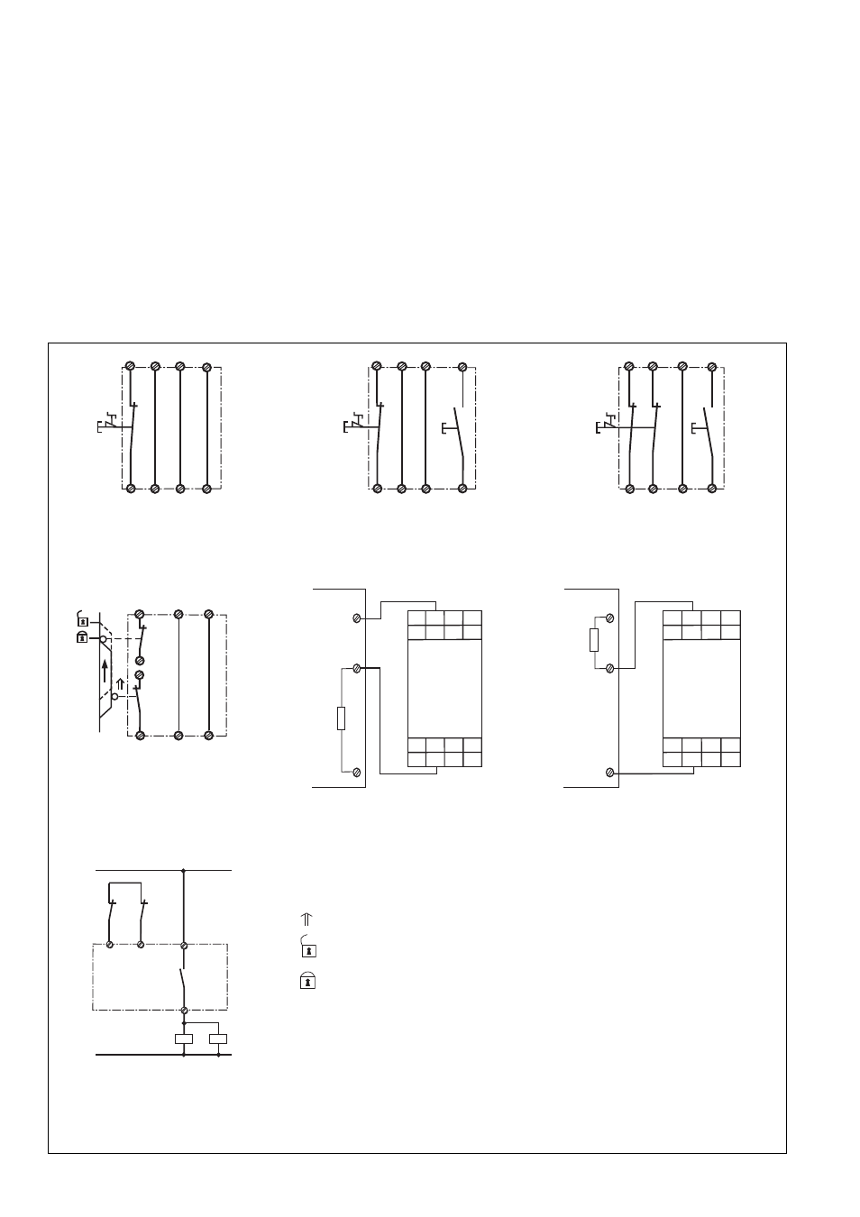
In Fig. 2 ... Fig. 8 sind Anschlussbeispiele für
Not-Halt-Beschaltung, Schutztüransteue-
rungen, den Halbleiterausgang sowie
Kontaktvervielfachung durch externe
Schütze.
Beachten Sie bei Fig. 2: Das Gerät startet bei
Spannungsausfall und -wiederkehr automa-
tisch. Verhindern Sie einen unerwarteten
Wiederanlauf durch externe Schaltungs-
maßnahmen.
Reactivation
• Close the input circuit.
• For manual reset press the button between
S33-S34.
The status indicators light up again, the
safety contacts are closed.
Application
In Fig. 2...Fig. 8 are connection examples for
Emergency Stop wiring, safety gate control,
the semiconductor output as well as contact
expansion via external contactors.
Please note for Fig. 2: the device starts
automatically after loss of power. You should
prevent an unintended start-up by using
external circuitry measures.
Remise en route :
• fermer le circuit d’entrée
• en cas de réarmement manuel, appuyer
sur le poussoir de validation entre S33-
S34.
Les affichages d'état s'allument à nouveau.
Les contacts de sécurité sont fermées.
Utilisation
Dans les figures 2 à 8 sont représentés les
différents cablages possibles du
PNOZ X2.5P : poussoirs AU, interrupteur de
position, le sortie statique et augmentation
du nombre des contacts par contacteurs
externes.
Dans le cas de la figure 2, l’appareil se
réarme automatiquement après une
coupure et une remise sous tension. Evitez
tout risque de redémarrage par un câblage
externe approprié.
S31
S32
S34
S22
S33
S21
S1
S3
S12
S11
S34
S33
S21
S32
S22
S31
S1
S1
S2
S12
S11
Fig. 5: Schutztürsteuerung zweikanalig,
automatischer Start/Dual-channel safety gate
control, automatic reset/Surveillance de
protecteur, commande par 2 canaux,
réarmement automatique
Fig. 4: Eingangskreis zweikanalig,
manueller Start/Two-channel input circuit,
manual reset/Commande par 2 canaux,
réarmement manuel
S31
S32
S34
S22
S33
S21
S11
S12
S1
S3
Fig. 3: Eingangskreis einkanalig, manueller
Start/Single-channel input circuit, manual
reset/Commande par 1 canal, réarmement
manuel
S31
S32
S34
S22
S33
S21
S11
S12
S1
Fig. 2: Eingangskreis einkanalig, automati-
scher Start/Single-channel input circuit,
automatic reset/Commande par 1 canal,
réarmement automatique
Fig. 6: Im Störfall Low-Pegel am Eingang der
Steuerung/If a fault occurs there is low level
at the controller's input/En cas de défaut,
signal bas sur entrée API
E0.0
+ 24V
0V
SPS
PNOZ X2.5P
24
Y12
A2
S32 S21 S22
34
S31
Y11 23 33
S11
S34
S33
A1
S12
E0.0
+ 24V
0V
SPS
PNOZ X2.5P
24
Y12
A2
S32 S21 S22
34
S31
Y11 23 33
S11
S34
S33
A1
S12
Fig. 7: Im Störfall High-Pegel am Eingang
der Steuerung/If a fault occurs there is high
level at the controller's input/En cas de
défaut, signal haut sur entrée API
K3
S33
S34
K4
K3
K4
23
24
L1
N
Tür nicht geschlossen/Gate open/porte ouverte
betätigtes Element/Switch activated/élément actionné
Fig. 8: Anschlussbeispiel für externe
Schütze, einkanalig/Connection example for
external contactors/relays, single-channel/
Branchement contacteurs externes,
commande par 1 canal
Tür geschlossen/Gate closed/porte fermée
S1/S2: Not-Halt- bzw. Schutztürschalter/Emergency Stop Button, Safety Gate Limit Switch/
Poussoir AU, détecteurs de position
S3:
Starttaster/Reset button/Poussoir de réarmement