Montage, Installation – Pilz PNOZ X2.3P C 24VACDC 3n/o User Manual
Page 2
- 2 -
• Eingangskreis geschlossen (z. B. Not-
Halt-Taster nicht betätigt):
Relais K1 und K2 gehen in Wirkstellung
und halten sich selbst. Die Statusanzeigen
für "CH.1" und "CH.2" leuchten. Die
Sicherheitskontakte 13-14/23-24/33-34
sind geschlossen.
• Eingangskreis wird geöffnet (z. B. Not-
Halt-Taster betätigt):
Relais K1 und K2 fallen in die Ruhestellung
zurück. Die Statusanzeige für "CH.1" und
"CH.2" erlischt. Die Sicherheitskontakte
13-14/23-24/33-34 werden redundant
geöffnet.
Modes de fonctionnement
• Commande par 1 canal : conforme aux
prescriptions de la EN 60204/1, pas de
redondance dans le circuit d’entrée. La
mise à la terre du circuit de réarmement
est détectée. En cas de mise à la terre
des circuits d'entrée, le fusible
électronique déclenche.
• Commande par 2 canaux: circuit d’entrée
redondant. La mise à la terre et les courts-
circuits entre les contacts sont détectées.
• Réarmement automatique : le relais est
activé dès la fermeture des canaux
d’entrée.
• Réarmement manuel : le relais n’est activé
qu’après une impulsion sur un poussoir de
validation.
• Réarmement manuel auto-contrôlé:
L'appareil est uniquement actif lorsque le
circuit de réarmement est ouvert avant
fermeture des circuits d'entrées et que le
circuit de réarmement est fermé après
fermeture des circuits d'entrées et
écoulement du temps d'attente (voir les
caractéristiques techniques). Cette
mesure permet d'éviter toute activation
automatique et toute inhibition du poussoir
de réarmement
• Augmentation du nombre de contacts ou
du pouvoir de coupure par l’utilisation de
contacteurs externes.
Montage
Le relais doit être monté en armoire ayant un
indice de protection mini IP54. Sa face
arrière permet un montage sur rail DIN.
Immobilisez l'appareil monté sur un rail DIN
vertical (35 mm) à l'aide d'un élément de
maintien comme par ex. un support ou une
équerre terminale.
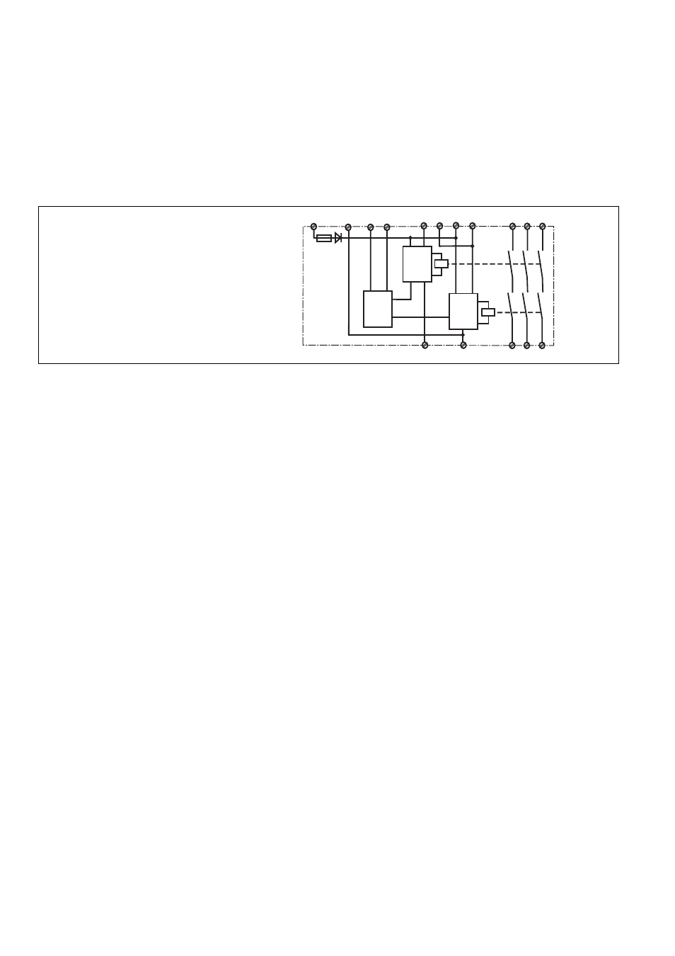
A1 (L+)
A2 (L-)
S22
S12
S21
S11
S33
13
14
K1
K2
23
24
S34
Start
Unit
Start
Unit
Auto
Start
Y36 Y37
33
34
Fig. 1: Innenschaltbild/Internal Wiring Diagram/
Schéma de principe
Betriebsarten:
• Einkanaliger Betrieb:
Eingangsbeschaltung nach VDE 0113 Teil
1 und EN 60204-1; keine Redundanz im
Eingangskreis; Erdschlüsse im Startkreis
werden erkannt. Bei Erdschlüssen im
Not-Halt-Kreis löst die Sicherung der
Versorgungsspannung aus.
• Zweikanaliger Betrieb: redundanter Ein-
gangskreis, Erdschlüsse im Tasterkreis
und Querschlüsse zwischen den Taster-
kontakten werden erkannt.
• Automatischer Start: Gerät ist aktiv, sobald
Eingangskreis geschlossen ist.
• Manueller Start: Gerät ist erst dann aktiv,
wenn ein Starttaster betätigt wird.
• Überwachter Start: Gerät ist nur aktiv,
wenn vor dem Schließen des Eingangs-
kreises der Startkreis geöffnet wird und
der Startkreis nach dem Schließen des
Eingangskreises und nach Ablauf der
Wartezeit (s. techn. Daten) geschlossen
wird. Dadurch ist eine automatische
Aktivierung und Überbrückung des
Starttasters ausgeschlossen.
• Kontaktvervielfachung und -verstärkung
durch Anschluss von externen Schützen.
Montage
Das Sicherheitsschaltgerät muss in einen
Schaltschrank mit einer Schutzart von mind.
IP54 eingebaut werden. Zur Befestigung auf
einer Normschiene dient ein Rastelement auf
der Rückseite des Geräts.
Sichern Sie das Gerät bei Montage auf einer
senkrechten Tragschiene (35 mm) durch
ein Halteelement wie z. B. Endhalter oder
Endwinkel.
Operating Modes
• Single-channel operation: Input wiring
according to VDE 0113 part 1 and
EN 60204-1, no redundancy in the input
circuit. Earth faults are detected in the
reset circuit. Earth faults in the Emergency
Stop circuit trigger the internal electronic
fuse.
• Two-channel operation: Redundancy in the
input circuit. Earth faults in the Emergency
Stop circuit and shorts across the
emergency stop push button are also
detected.
• Manual reset: Unit is only active when a
reset button has been pressed.
• Monitored manual reset: Unit will only be
active if the reset circuit is opened before
the input circuit closes, and the reset
circuit is closed after the input circuit has
closed and the waiting time has elapsed
(see technical data). This eliminates the
possibility of the reset button being
overridden, triggering automatic
activation.
• Increase in the number of available
contacts by connection of external
contactors/relays.
Installation
The safety relay must be panel mounted
(min. IP54). There is a notch on the rear of
the unit for DIN-Rail attachment.
If the unit is installed on a vertical mounting
rail (35 mm), ensure it is secured using a
fixing bracket such as end bracket.
• Input Circuit closed (e.g. the Emergency
Stop button is not pressed):
Relays K1and K2 energise and retain
themselves. The status indicators for
"CH.1" and "CH.2" illuminate. The safety
contacts (13-14/23-24/33-34) are closed.
• Input Circuit is opened (e.g. Emergency
Stop is pressed):
Relays K1 and K2 de-energise. The status
indicators for "CH.1" and "CH.2" go out.
The safety contacts (13-14/23-24/33-34)
will be opened (redundant).
• Circuits d'entrée fermés (poussoir AU
non actionné) :
Les relais K1 et K2 passent en position
travail et s'auto-maintiennent. Les LEDs
"CH.1" et CH.2" s'allument. Les contacts
de sécurité (13-14/23-24/33-34) sont
fermés.
• Circuits d'entrée ouverts (poussoir AU
actionné) :
Les relais K1 et K2 retombent. Les LEDs
"CH.1" et "CH.2" s'éteingnent. Les contacts
de sécurité (13-14/23-24/33-34) s'ouvrent.