Operation, Status indicators, Error indicators – Pilz PNOZ s7 C 4 n/o 1 n/c coated User Manual
Page 6
PNOZ s7
Operating Manual PNOZ s7
21399-EN-09
6
}
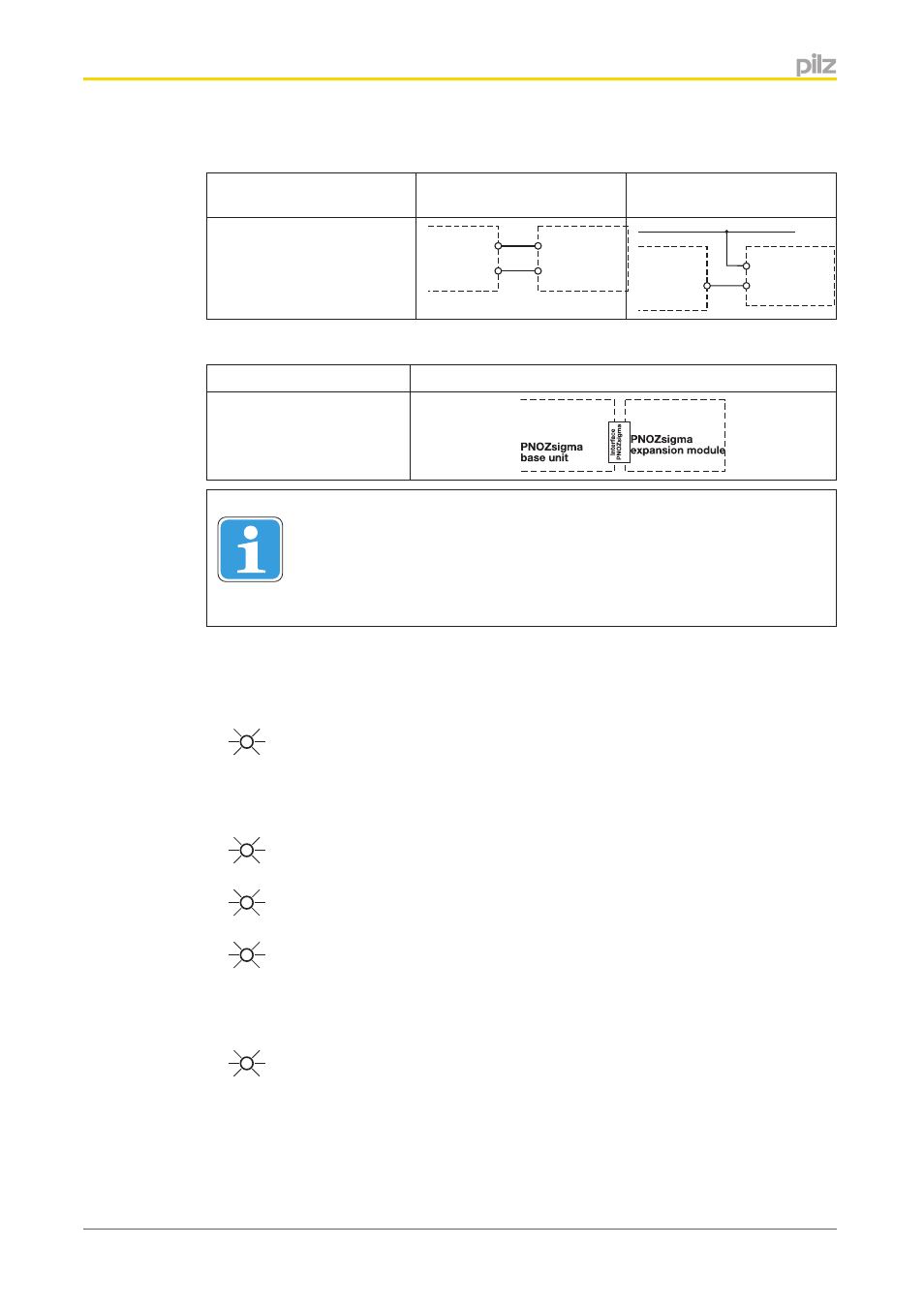
Feedback loop
Feedback loop
Base unit: Safety relay
PNOZ X
Base unit: Safety relay
PNOZelog
The inputs that evaluate the
feedback loop will depend on
the base unit and application
52
51
feedback
loop
PNOZsigma
expansion
module
51
52
24 V DC
feedback
loop
PNOZsigma
expansion
module
}
Connection to PNOZsigma base unit
Base unit: Safety relay PNOZsigma
The feedback loop is con-
nected and evaluated via
the connector
Information
If a base unit and a contact expansion module from the PNOZsigma range
are linked via the connector, no additional wiring is necessary.
Do not connect A1 to the contact expander module!
Operation
LEDs indicate the status and errors during operation:
LED on
Status indicators
In1
Channel 1 actuated.
In2
Channel 2 actuated.
In1, In2, Out
Safety contacts are closed.
Error indicators
Fault
Diagnostics: Plug terminator not connected
}
Remedy: Insert plug terminator, switch supply voltage off and then on
again.