Wiring, Preparing for operation – Pilz PNOZ s7 C 4 n/o 1 n/c coated User Manual
Page 5
PNOZ s7
Operating Manual PNOZ s7
21399-EN-09
5
Wiring
Please note:
}
Information given in the "Technical details" must be followed.
}
Outputs 13-14, 23-24, 33-34, 43-44 are safety contacts; outputs 51 -52 are auxiliary
contacts (e.g. for display).
}
Auxiliary contact 51-52 should
not be used for safety circuits!
}
To prevent contact welding, a fuse should be connected before the output contacts (see
technical details).
}
Calculation of the max. cable length l
max
in the input circuit:
R
lmax
R
l
/ km
I
max
=
R
lmax
= max. overall cable resistance (see technical details)
R
l
/ km = cable resistance/km
}
Use copper wire that can withstand 60/75 °C.
}
Sufficient fuse protection must be provided on all output contacts with capacitive and in-
ductive loads.
Preparing for operation
}
Supply voltage
Supply voltage
AC
DC
A1
A2
24 V DC
0 V
PNOZsigma
expansion
module
}
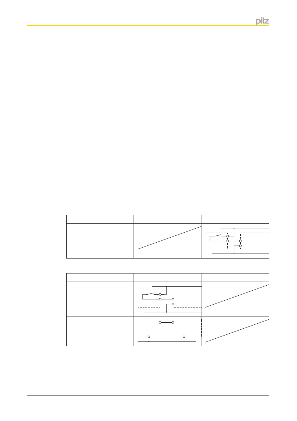
Input circuit
Input circuit
Single-channel
Dual-channel
Base unit:
Safety relay PNOZ X
A1
A2
24 V DC
0 V
PNOZsigma
expansion
module
Base unit:
PNOZelog safety relay
driven via semiconductor
outputs (24 VDC)
A1
A2
0 V
O1
L-
PNOZsigma
expansion
module