Safety features, Block diagram/terminal configuration – Pilz PNOZ s9 C 24VDC 3 n/o t 1 n/c t coated User Manual
Page 4
PNOZ s9
Operating Manual PNOZ s9
21401-EN-08
4
}
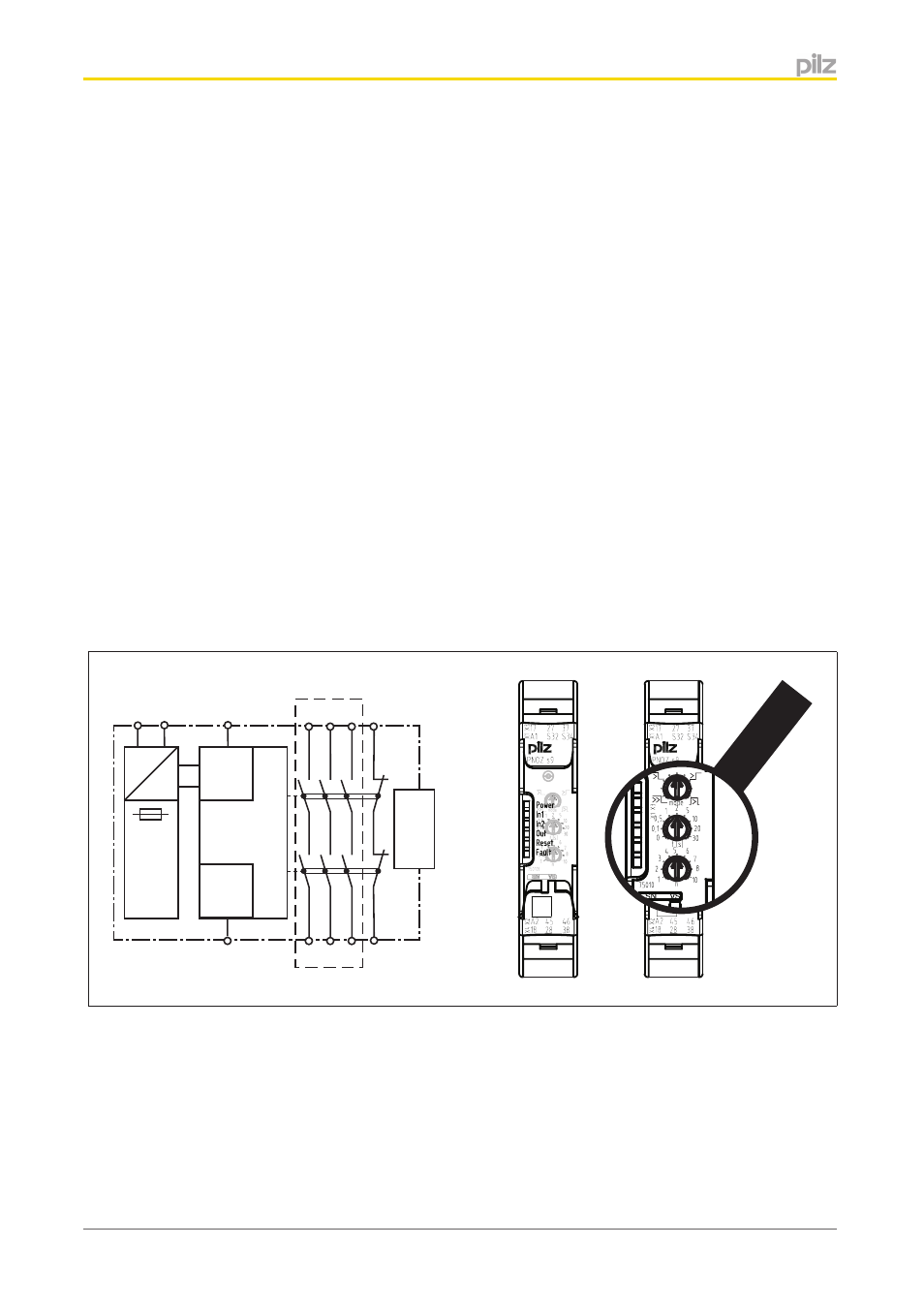
LED indicator for:
– Supply voltage
– Input status, channel 1
– Input status, channel 2
– Switch status channel 1/2
– Start circuit
– Error
}
Plug-in connection terminals (either spring-loaded terminal or screw terminal)
Safety features
The unit meets the following safety requirements:
}
The unit monitors its own output contacts.
}
The safety function remains effective in the case of a component failure.
}
Earth fault in the feedback loop is detected.
}
Earth fault in the input circuit:
The output relays de-energise and the safety contacts open.
}
The unit has an electronic fuse.
Block diagram/terminal configuration
Input
A1 A2
=
Power
=
K1
K2
17 27 37 45
28 38 46
18
Interface
base unit
*
S32
Reset
S34
Centre: Front view with cover, right: Front view without cover
*Safe separation in accordance with EN 60947-1, 6 kV