Funktionsbeschreibung, Function description, Description du fonctionnement – Pilz S3UM 24VDC UM 208/400/480VAC User Manual
Page 2
• separate Steuerspannung A1-A2
• Fehlerzustand kann gespeichert oder
nicht gespeichert werden
Das Gerät erfüllt folgende Sicherheitsanfor-
derungen:
• Funktion nach dem Ruhestromprinzip
wählbar
• Schutz der zu überwachenden Anlage ist
gewährleistet bei:
- Spannungsausfall
- Spulendefekt
- Leiterbruch
Funktionsbeschreibung
Das Spannungsüberwachungsrelais
S3UM/E schützt Maschinen und Anlagenteile
vor Schäden durch Unter- oder Überspan-
nung, Phasenfolgefehler und Phasenausfall.
Der Phasenausfall wird auch bei Spannungs-
rückkopplung durch angeschlossene
Verbraucher erkannt. Die Rückspeisung
muss dabei kleiner sein als der eingestellte
Unterspannungswert. Der Ansprechwert für
Unterspannung (U
min
) kann zwischen 75 %
und 100 %, der Ansprechwert für Überspan-
nung (U
max
) zwischen 100 % und 120 % der
angegebenen Netznennspannung
eingestellt
werden. Alle Spannungen werden gegen den
Sternpunkt (Nulleiter) des Netzes gemessen.
Bei Netzen ohne Nulleiter dient der künstliche
Sternpunkt im Gerät als Bezugspunkt. Durch
Mittelwertbildung werden Fehlfunktionen
aufgrund überlagerter Steuersignale oder
Frequenzen vermieden.
Die LED "U
N
" leuchtet, sobald die Steuer-
spannung (A1/A2) anliegt.
Funktion Ruhestromprinzip ( ) und
Nicht-Speichern (AR = automatischer
Reset)
Sind die drei Spannungen U
L1
, U
L2
und U
L3
größer als der Ansprechwert U
min
und
kleiner als der Ansprechwert U
max
, ist das
Ausgangsrelais K1 im Arbeitszustand. Der
Kontakt 11-14 ist geschlossen, der Kontakt
11-12 ist geöffnet.
Bei Unterspannung (U
L1
, U
L2
oder U
L3
<
U
min
) leuchtet die rote LED und das Aus-
gangsrelais K1 fällt ab. Der Ausgangskontakt
11-14 öffnet und 11-12 schließt.
Bei Überspannung (U
L1
,U
L2
oder U
L3
> U
max
)
leuchtet ebenfalls die rote LED und das Aus-
gangsrelais K1 fällt ab. Der Ausgangskontakt
11-14 öffnet und 11-12 schließt.
Hat das Netz den zulässigen Spannungs-
bereich wieder erreicht, zieht das Aus-
gangsrelais wieder an und die LED geht aus.
• Separate control voltage A1-A2
• Fault status can be latching or non-
latching
The unit complies with the following safety
requirements:
• Normally energised mode can be
selected
• Protection of the monitored unit is
maintained in the following cases:
- Loss of voltage
- Coil defect in a relay
- Cable break
Function Description
The Voltage Monitor Relay S3UM/E
protects machine and plant parts from
damage caused by under or over voltage,
phase sequence faults and phase failure.
Phase failure can also be detected via the
voltage feedback from the connected load.
The feedback must be less than the set
under voltage value. The response value
for under voltage (U
min
) can be set
between 75% and 100% of the voltage and
the response value for over voltage (U
max
)
can be set between 100% and 120% of the
given voltage. All voltages will be evaluated
against the starpoint (neutral conductor) on
the network. With networks without a
neutral conductor, the dummy (artificial)
starpoint in the unit serves as a reference
point. By evaluating the mean, fault
functions caused by overriding frequencies
or control signals will be avoided. The LED
U
N
is illuminated when the control voltage
(A1/A2) is supplied.
Normally energised mode ( ) and non-
latching (AR = automatic reset)
When the three voltages U
L1
, U
L2
und U
L3
are greater than the response value U
min
and less than response value U
max
then
both output relays are in the operating mode
(energised). The contacts 11-14 is closed
and the contact 11-12 is open.
With under voltage (U
L1
, U
L2
und U
L3
< U
min
)
the red LED is illuminated and the output
relay K1 de-energises. The output contact
11-14 opens and 11-12 closes.
With over voltage (U
L1
, U
L2
und U
L3
> U
max
)
the red LED is also illuminated and the
output relay K1 de-energises. The output
contact 11-14 opens and 11-12 closes.
When the network reaches the permitted
voltage range again the appropriate output
relay energises and the corresponding
LED goes out.
~
=
MR: manueller Reset
Manual reset
Reset manuel
AR: automatischer Reset
automatic reset
Reset automatique
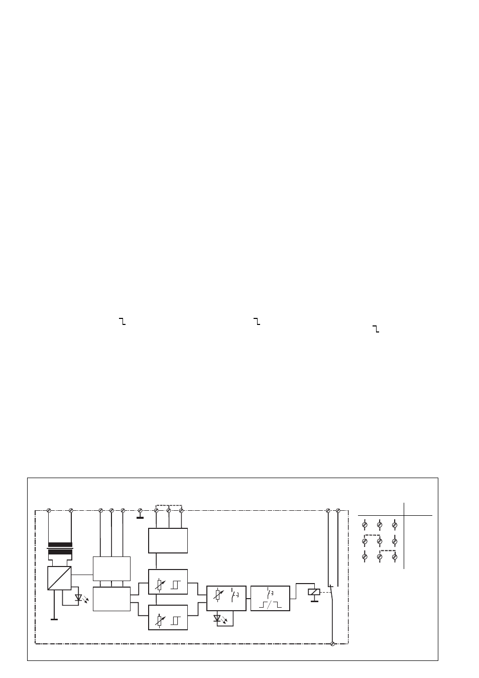
Schematisches Schaltbild/Wiring diagram/Schéma interne
A1
A2
L1 L2 L3
N
Y1 Y2
12 14
11
G1
Power
(PWR)
Fault
(FLT)
Umformung
Transformation
U
1 - 3
Erkennung
Detection
Détection
U
min
/U
max
Umschaltung
Switching
Commutation
U
M
Skala/Scale/Echelle
Skala/Scale/Echelle
Drehstromnetz
Three-Phase Network
Réseau triphasé
MR/AR
t
r
100 - 120 % U
B
75 - 100 % U
B
K1
Arbeits-/Ruhestrom
Normally de-energised/enrgised mode
Excitation/Retombée
• Tension d'alimentation séparée A1-A2
• Mise en mémoire ou non du défaut
Le relais répond aux exigences de sécurité
suivantes :
• Indication du défaut par retombée du
relais de sortie
• Protection de l’installation garantie en cas
i
de:
- défaillance tension d’alimentation
- défaillance bobine
- rupture de liaison
Description du fonctionnement
Le relais S3UM/E permet de protéger les
machines et installations contre les dangers
liés à une sous ou surtension de leur
tension d'alimentation, un défaut d'ordre des
phases ou une coupure de phase. La
détection d'une coupure de phase est
garantie même en cas de retour de tension
par l'utilisateur. La valeur du retour de
tension doit cependant être plus petite que
le seuil de sous-tension affiché. Le seuil de
déclenchement de sous-tension (U
min
)
peut être réglé entre 75% et 100% de la
tension nominale et le seuil de déclenche-
ment de surtension (U
max
) entre 100% et
120% de la tension nominale. Toutes les
tensions sont mesurées par rapport au
neutre du réseau ou au "neutre artificiel"
interne du relais en cas de réseaux sans
neutre. Le principe de mesure permet
d'éviter les défauts de fonctionnement liés
aux variations de fréquences et tensions
parasites. La LED U
N
s'allume dès que la
tension d'alimentation (A1/A2) est présente.
Fonction retombée ( ) et pas de
mémorisation (AR = reset automatique)
Si les tensions U
L1
, U
L2
et U
L3
sont plus
grandes que le seuil U
min
et plus petites que
le seuil U
max
, le relais de sortie K1 passe en
position travail. Le contacts 11-14 est
fermé et le contact 11-12 est ouvert.
En cas de sous-tension (U
L1
, U
L2
ou U
L3
<
U
min
), la LED rouge s'allume et le relais de
sortie K1 retombe. Le contact 11-14 s'ouvre
et 11-12 se ferme.
En cas de surtension (U
L1
,U
L2
ou U
L3
>
U
max
), la LED rouge s'allume et le relais de
sortie K1 retombe. Le contact 11-14 s'ouvre
et 11-12 se ferme.
Dès que la tension surveillée revient dans le
domaine autorisé, le relais de sortie repas-
se en position travail et la LED rouge
s'éteint.
Y3
Y1 Y2
Y3
U
M
400 V
208 V
480 V