Anwendung, Utilisation, Application – Pilz S1IM 230-240VAC IM 0.01-15 A User Manual
Page 4
- 4 -
Anschluss:
• Versorgungsspannung an die Klemmen
A1(+) und A2 (-) anschließen.
• Messeingang an 0,1 A oder 2 A oder E
anschließen
• Messbereichsendwert durch Schiebe-
schalter festlegen:
Beispiel: Messeingang 2 A, Messbereich
0,4 A: Schiebeschalter S1 auf Position 1
und S2 auf Position 0,2 bringen
WICHTIG!
• Messeingang E: Messbereich 25 A nur
für max. 10 s und Messbereich 50 A nur
für max. 2 s zulässig.
• Mess- und Versorgungsspannung bei
DC-Geräten sowie parallel geschaltete
Geräte immer galvanisch trennen, da
sonst das Gerät zerstört werden kann.
• Ansprechwert I
an
festlegen: mit kleinem
Schraubendreher Potentiometer %I auf
gewünschten Wert stellen.
• Hysterese I
ab
festlegen: mit kleinem
Schraubendreher Potentiometer HYST.
auf gewünschten Wert stellen.
• Ruhe-/Arbeitsstromprinzip wählen:
- Ruhestromprinzip : Y1-Y2 offen
- Arbeitsstromprinzip:Y1-Y2 brücken
• Speichern/nicht speichern wählen:
- nicht speichernd: Y2-Y3 offen
- speichernd: Taster oder Brücke (Netz-
Reset) zwischen Y2-Y3 anschließen
Das Gerät ist betriebsbereit, sobald die
Versorgungsspannung eingeschaltet ist.
Wenn ein Taster zwischen Y2 und Y3
angeschlossen ist, muss dieser geschlossen
sein.
Anwendung
Das Gerät nur wie in den folgenden
Anschlussbildern anschließen!
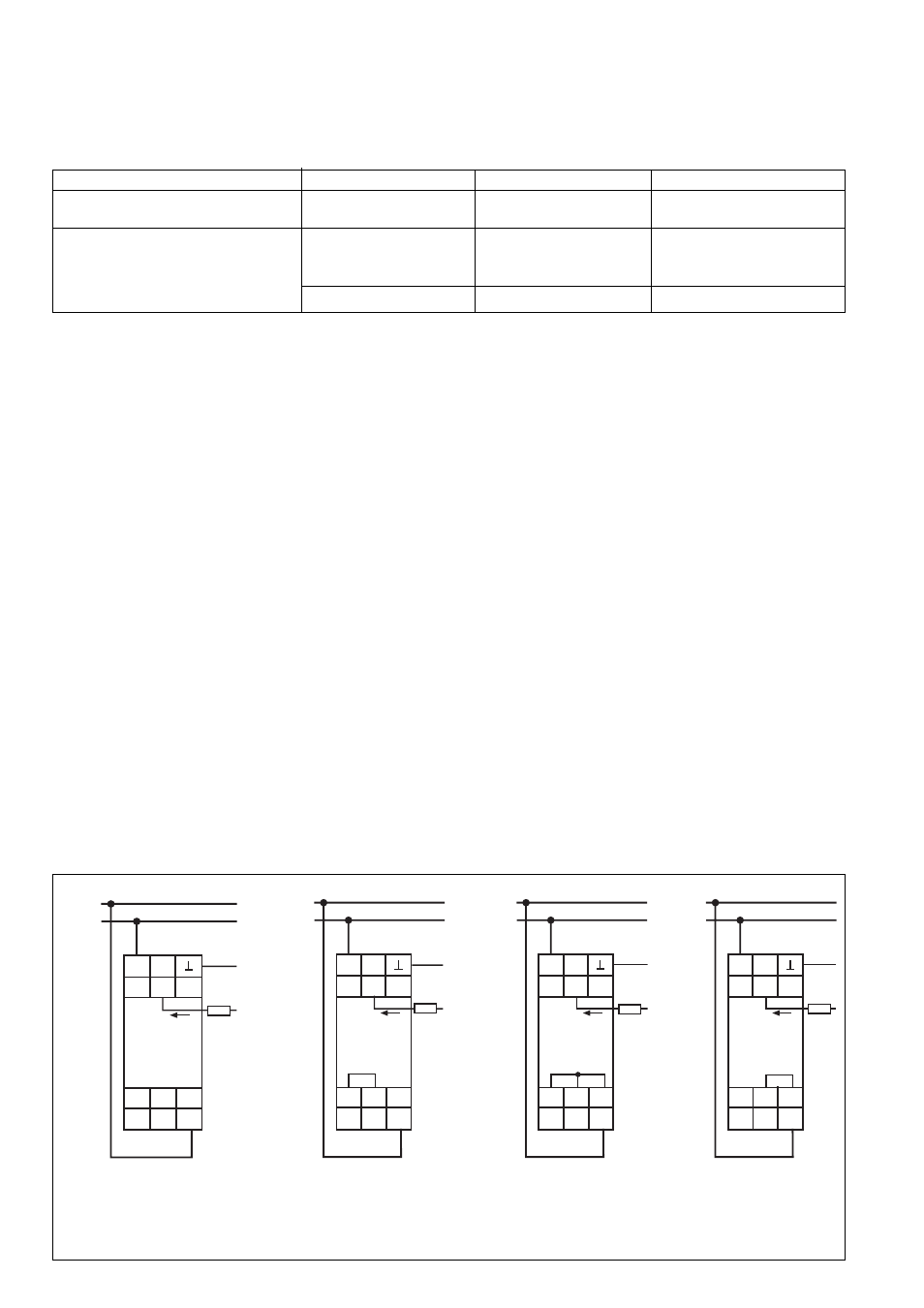
Fig. 3: Anschlussbilder: Ruhestrom, nicht speichern (1)/Arbeitsstrom, nicht speichernd (2)/Arbeitsstrom, speichernd (3)/Ruhestrom, speichernd (4)
Connection Diagrams: Energised mode, non-latching (1) / De-energised mode, non-latching (2) / De-energised mode, latching (3) / Energised
mode, latching (4)
Schémas de branchement : par retombée du relais, non mémorisé (1)/Par excitation du relais, non mémorisé (2)/Par excitation, mémorisé(3)/Par
retombée du relais, mémorisé (4)
A2
A1 11
1L1
1L2
U
B
12 14
0,1 A
2 A
Y1 Y2 Y3
I
M
R
L
E
11
A1
0,1 A
2 A
Y2
Y1
14
12
A2
Y3
I
M
R
L
1L1
1 L2
U
B
E
11
A1
0,1 A
2 A
Y2
Y1
14
12
A2
Y3
I
M
R
L
1L1
1 L2
U
B
E
11
A1
0,1 A
2 A
Y2
Y1
14
12
A2
Y3
I
M
R
L
1L1
1 L2
U
B
E
(1)
(2)
(3)
(4)
Utilisation
Le relais doit être câblé uniquement
comme indiqué dans le schéma ci-
dessous.
Connection:
• Connect operating voltage to terminals A1
(+) and A2 (-)
• Connect measuring input 0.1 A, 2 A or E
• Set the measuring range limit value using
the sliding switches.
Example: Measuring input 2 A, measuring
range 0.4 A: set sliding switch S1to
position 1 and S2 to position 0.2
IMPORTANT!
• Measuing input E: Measuring range 25
A can be set for a max. of 10 s and
measuring range 50 A for a max. of 2 s.
• Measuring and operating voltage on DC
units and parallel-switched units must
be galvanically isolated, otherwise the
units could become damaged.
• To set response value I
an
: using a small
screwdriver set the potentiometer %I to the
required value
• To set hystsresis Iab: using a small
screwdriver set the potentiometer “HYST”
to the required value
• Normally energised / de-energised mode
- Normally energised mode: Y1-Y2 open
- Normally de-energised mode: link Y1-Y2
• Selecting latching/non-latching
- non-latching: Y2-Y3 open
- latching: connect a button or link (reset)
between Y2-Y3.
The unit is ready for operation as soon as the
operating voltage is applied. If a button
between Y2 and Y3 is connected, this must
be closed.
Application
Connect the unit according to the
following diagram.
Messeingang/Measuring input/entrées mesure
0,1 A
2 A
E
Messbereich/Measuring Range/G. mesure
0,01
0,02
0,05
0,1
0,2
0,4
1
2
5
10
25
50
in/en A
max. 10 s max. 2 s
Position Schiebeschalter/Sliding switch/
Position commutateur
S1
0,5
1
0,5
1
0,5
1
0,5
1
0,5
1
0,5
1
S2
0,2
0,2
1
1
0,2
0,2
1
1
0,2
0,2
1
1
Branchement :
• Ramener la tension d'alimentation sur les
bornes A1(+) et A2 (-).
• Raccorder le circuit mesure 0,1 A ou 2 A
ou E
• Sélectionner la gamme de mesure à l'aide
des commutateurs :
Exemple : entrée mesure 2 A, gamme 0,4
A: mettre commutateur S1 sur position 1
et S2 sur position 0,2
REMARQUE !
• Circuit mesure E: gamme 25 A, utilisa-
tion max. 10 s et gamme 50 A, utilisa
tion max. 2 s
• Pour les appareils alimentés en DC, le
circuit mesure doit être isolé galvanique-
ment du circuit d’alimentation. Les
appareils branchés en parallèle doivent
également être isolés galvaniquement
entre eux. Dans le cas contraire, le relais
risque d’être détruit.
• Régler le point de déclenchement I
an
à
l'aide du potentiomètre %I.
• Régler l'hystérésis I
ab
à l'aide du
potentiomètre HYST
• Sélectionner le mode de fonctionnement
du relais de sortie:
- par retombée : Y1-Y2 ouvert
- par excitation : ponter Y1-Y2
• Sélectionner la mémorisation ou non:
- pas de mémorisation : Y2-Y3 ouvert
- mémorisation : câbler un poussoir sur
Y2-Y3 ou ponter les 2 bornes (Power
reset).
L'appareil est prêt à fonctionner dès que la
tension d'alimentation est présente. Si un
poussoir est raccordé entre Y2 et Y3, ce
dernier ne doit pas être actionné.