Funktionsbeschreibung, Function description, Description du fonctionnement – Pilz S1IM 230-240VAC IM 0.01-15 A User Manual
Page 2
- 2 -
Funktionsbeschreibung
Das Stromüberwachungsrelais arbeitet als
Schwellwertschalter. Der Ansprechwert für
Überschreiten des Messstroms I
an
und die
Hysterese I
ab
sind einstellbar.
Voraussetzung: Die Versorgungsspannung
ist angelegt und das Arbeitsstromprinzip
(Beispiel) ist eingestellt. Die LED "PWR"
leuchtet. Die Funktion "nicht speichern"
wurde gewählt.
Überschreitet I
M
den eingestellten Ansprech-
wert I
an
, zieht das Relais nach Ablauf der
Reaktionszeit an. Der Hilfskontakt 11-14 ist
geschlossen und 11-12 geöffnet. Die LED
"OUT" leuchtet.
Unterschreitet der Messstrom den durch die
Hysterese festgelegten Wert I
ab
, fällt das
Relais ab. Der Hilfskontakt 11-14 ist geöffnet
und 11-12 geschlossen. Die LED "OUT"
erlischt.
Ist statt des Arbeitsstromprinzips das Ruhe-
stromprinzip eingestellt, fällt das Relais bei
Überschreiten des Ansprechwerts I
an
ab und
es zieht bei Unterschreiten des Abschalt-
werts I
ab
an.
Funktion "speichern/nicht speichern"
"Nicht speichern": Y2-Y3 offen
Nach Überschreiten des Ansprechwerts I
an
wechselt das Relais seinen Zustand.
Unterschreitet der Strom den Wert I
ab
,
wechselt das Relais automatisch wieder in
seinen Ausgangszustand.
"Speichern": Öffnerkontakt einesTasters
oder Brücke zwischen Y2 und Y3
Voraussetzung: Der Taster ist geschlossen.
Nach Überschreiten des Ansprechwerts I
an
wechselt das Relais seinen Zustand. Das
Relais behält seinen Zustand auch dann,
wenn der Strom I
ab
wieder unterschritten
wurde. Es wechselt erst nach Öffnen des
Tasters zwischen Y2 und Y3 oder nach Aus-
und Einschalten der Versorgungsspannung.
Hysterese
Der Ansprechwert I
an
wird durch den Mess-
strom und den Faktor "%I" festgelegt. Es
stehen 3 Messeingänge 0,1 A, 2 AV und E
zur Verfügung. Diese Messbereichsendwerte
können durch 2 Schiebeschalter verkleinert
werden. I
an
ergibt sich aus dem eingestellten
Messbereichsendwert und dem am Potentio-
meter "%I" eingestellten Faktor.
I
ab
wird durch das Potentiometer "HYST."
festgelegt. Der am Potentiometer eingestellte
Faktor multipliziert mit dem Wert I
an
ergibt
den Abschaltwert I
ab
.
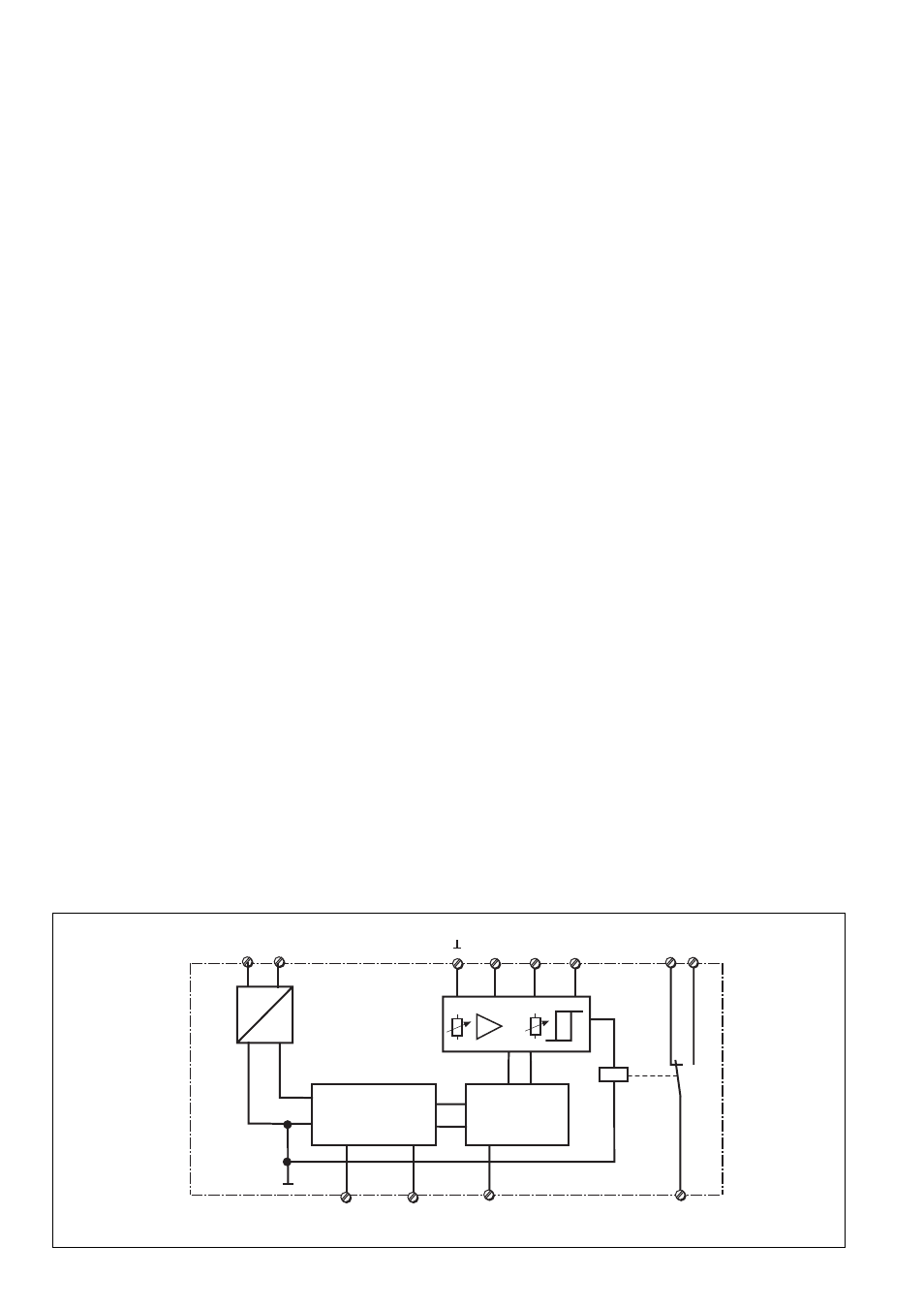
G1
K1
12
14
11
~
=
A2
(-)
A1
(+)
B
U
Y1
Y2
Y3
2 A
E
0,1 A
Arbeits-/Ruhestrom
De-energised/
energised mode
Mode excitation/
retombée
Speichern/
latching/
memorisé
Fig.1: Schematisches Schaltbild/ Wiring diagram/Schéma interne
Function Description
The current monitoring relay operates as a
threshold value element (threshold value
switch). The response value for exceeding
the measuring current I
an
and the hysteresis
I
ab
can be set.
Requirement: Operating voltage is applied
and relay set to normally de-energised mode,
for example. The LED “PWR” is illuminated.
The function “Non-latching was selected.
If I
M
exceeds the set response value I
an
, the
relay energises after the reaction time has
elapsed. The auxiliary contact 11-14 is
closed and 11-12 is open. The LED “OUT” is
illuminated.
If the measuring current falls below the set
value determined via hysteresis I
ab
, then the
relay de-energises. The auxiliary contact 11-
14 is open and 11-12 is closed. The LED
“OUT” goes out.
If the relay is set to normally energisd mode,
the relay de-energises when I
ab
is exceeded
and energises if it falls below the trip value
I
ab
.
Latching / Non-Latching Function
“Non-latching”: Y2-Y3 open
After the response value I
an
has been
exceeded the relay changes its status. If the
current falls below I
ab
the relay automatically
changes its status again.
“Latching”: N/C contact of a button or link
between Y2 and Y3.
Conditions for operation: Button is closed.
After U
an
has been exceeded the relay
changes its status. The relay will keep that
status even if the current falls below I
ab
. It
will only change once the N/C contact on the
button between Y2 and Y3 has been opened
or after the operating voltage has been
switched off and back on.
Hysteresis
The response value I
an
will be determined via
the measuring current and the factor “%I”.
There are 3 measuring inputs available 0.1A,
2 A and E (see technical details). The
measuring range limit values can be reduced
using the 2 sliding switches. I
an
is given from
the set measuring range limit value and the
“%I” factor set on the potentiometer. I
ab
is set
on the potentiometer “HYST”. If the factor
set on the potentiometer is multiplied by I
an
, it
gives the trip value I
ab
.
Description du fonctionnement
Le relais de surveillance d'intensité S1IM est
un relais à seuil. Le point de déclenchement
I
an
et l'hystérésis I
ab
sont réglables.
Préalables: la tension d'alimentation est
présente et le mode de fonctionnement par
excitation du relais de sortie est sélectionné
(exemple). La LED "PWR" est allumée. La
fonction "non mémorisée" est sélectionnée.
Si l'intensité mesurée I
M
dépasse le point de
déclenchement I
an
, le relais de sortie passe
en position travail au bout du temps de
réponse. Le contact 11-14 se ferme et 11-12
s'ouvre. La LED "OUT" est allumée.
Si l'intensité mesurée passe en dessous du
seuil réglé par l'hystérésis I
ab
, le relais de
sortie retombe. Le contact 11-14 s'ouvre et
11-12 se ferme. La LED "OUT" est éteinte.
Si le mode de fonctionnement par retombée
du relais de sortie est sélectionné, le relais
retombe en cas de dépassement du seuil
réglé I
an
et remonte si l'intensité repasse en
dessous de I
ab
.
Fonction mise en mémoire
"Pas de mise en mémoire" : Y2-Y3 ouvert
En cas de dépassement du point de
déclenchement I
an
, le relais change d'état. Si
l'intensité mesurée repasse en dessous du
seuil I
ab
, le relais repasse automati-
quement dans son état initial.
"Mise en mémoire ": pont entre Y2-Y3 ou
câblage d'un contact à ouverture d'un BP.
Préalable : le circuit est fermé. En cas de
dépassement du point de déclenchement I
an
, le relais change d'état. Le relais con- serve
cet état même si l'intensité mesurée repasse
en dessous du seuil I
ab
. Le relais repasse
en position initiale qu'après ouverture du
circuit Y2-Y3 ou coupure de la tension
d'alimentation.
Hystérésis
Le point de déclenchement I
an
est réglé en
fonction de la gamme de mesure utilisée et
du facteur "%I". Trois circuits de mesure sont
disponibles: 0,1 A, 2 AV et E . Ces circuits de
mesure disponsent chacun de 4 gammes qui
sont sélectionnées à l'aide de 2
commutateurs. I
an
est réglée en fonction de
la gamme de mesure utilisée et du poten-
tiomètre "%I".
I
ab
est réglée à l'aide du potentiomètre
"HYST.". La valeur de retombée I
ab
est le
produit de la valeur affichée I
an
par le facteur
d'hystérésis sélectionné.