Montage, Inbetriebnahme, Installation – Pilz S1IM 230-240VAC IM 0.01-15 A User Manual
Page 3: Operation, Mise en oeuvre
- 3 -
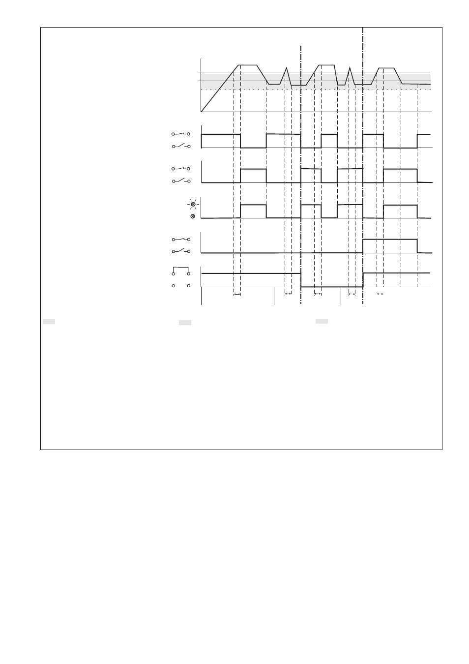
Fig. 2: Funktionsdiagramm/
Pulse diagram/
Diagramme fonctionnel
I
M
I
ab
I
an
12
12
LED
Y2
Y3
Y2
Y3
Y1
Y2
Y1
Y2
11
11
Arbeitsstromprinzip/
de-energised mode/
mode excitation
Ruhestromprinzip/
energised mode/
mode retombée
nicht speichernd/non-latching/non mémorisé
speichernd/latching/mémorisé
Arbeitsstromprinzip/
de-energised mode/
mode excitation
14
14
11
11
t
R
IIb
Ib
t
R
Ia
IIa
t
R
t
R
t
R
III
Hysterese (I
ab
): 0,8 x I
an
einstellbare Hysterese
t
R
: Reaktionszeit
Ia: I
M
> I
an
: nach Ablauf von t
R
zieht das
Relais an und die LED "OUT" leuchtet.
I
M
< I
ab
: Relais fällt ab und LED
erlischt
Ib: I
M
> I
an
: wie oben, aber Relais fällt ab
und LED "Out" erlischt
I
M
< I
ab
: Relais zieht an und LED
leuchtet
IIa: I
M
> I
an
vor Ablauf von t
R
: Relais bleibt
abgefallen
IIb: wie oben, aber Relais bleibt angezogen
III: I
M
> I
an
: s. oben
I
M
< I
ab
: Relais fällt erst ab, wenn
Y2-Y3 geöffnet ist.
Montage
Das Gerät muss in einen Schaltschrank mit
einer Schutzart von mind. IP54 eingebaut
werden. Zur Befestigung auf einer Norm-
schiene hat das Gerät ein Rastelement auf
der Rückseite.
Inbetriebnahme
Beachten Sie bei der Inbetriebnahme:
• Der Ausgangskontakt 11-12-14 ist ein
Hilfskontakt (z. B. für Anzeige oder
Schützansteuerung).
• Vor den Ausgangskontakt eine Siche-
rung (6 A flink oder 4 A träge) schalten,
um das Verschweißen des Kontaktes zu
verhindern.
• Leitungsmaterial aus Kupferdraht mit einer
Temperaturbeständigkeit von 60/75 °C
verwenden.
• Das Anzugsdrehmoment der Schrauben
auf den Anschlussklemmen darf max.
0,6 Nm betragen.
• Angaben im Kapitel "Technische Daten"
unbedingt einhalten.
Installation
The unit must be panel mounted (min. IP54).
There is a notch on the rear of the unit for
DIN-Rail attachment.
Hysteresis (I
ab
): 0,8 x I
an
hysteresis can be set
t
R
: Reaction time
Ia: I
M
> I
an
: after t
R
has elapsed the relay
energises and the LED “OUT” is
illuminated.
I
M
< I
ab
: relay de-energises and LED
goes out
Ib: I
M
> I
an
: as above, but relay de-
energises and the LED “Out” goes out
I
M
< I
ab
: relay energises and the LED
is illuminated
IIa: I
M
> I
ab
before t
R
has elapsed: relay
remains de-energised
IIb: as above, but the relay remains energised
III: I
M
> I
an
: see above
I
M
< I
ab
: relay de-energises once Y2-Y3
is open
Operation
Please note with operation:
• The output contact 11-12-14 is an auxiliary
contact (e.g. for signalling or contactor
control)
• To prevent contact welding, a fuse
(6 A quick or 4 A slow) must be
connected before the output contacts.
• Use copper wires that can withstand
temperatures of 60/75 °C.
• Tighten terminals to a max. 0.6 Nm
• Important details in the section “Technical
Data” should be noted and adhered to
Le relais doit être installé dans une armoire
ayant un indice de protection IP54. Sa face
arrière permet un montage sur rail DIN.
Mise en oeuvre
Remarques préliminaires :
• Le contact de sortie 11-12-14 et un contact
d'information (ex. pour signalisation ou
pilotage de relais).
• Protéger les contacts de sortie par des
fusibles (6 A rapides ou 4 A normaux)
pour éviter leur soudage.
• Le couple de serrage sur les bornes de
raccordement doit être d'au max. 0,6 Nm.
• Utiliser des câbles en cuivre supportant
des températures de 60/75°C
• Respecter les données indiquées dans le
chapitre „Caractéristiques techniques“.
Montage
Hystérésis (U
ab
): 0,8 x I
an
hystérésis réglable
t
R
: temps de réponse
Ia: I
M
> I
an
: au bout du temps t
R
, le relais
monte et la LED "OUT" est allumée.
I
M
< I
ab
: le relais retombe et la LED
s'éteint.
Ib: I
M
> I
an
: idem, mais le relais retombe et
la LED "Out" est éteinte.
I
M
< I
ab
: le relais monte et la LED
est allumée.
IIa: I
M
> I
an
avant fin de t
R
: le relais reste
au repos
IIb: idem, mais le relais reste excité
III: I
M
> I
an
: voir ci-dessus
I
M
< I
ab
: le relais retombe uniquement
si Y2-Y3 est ouvert.