Pilz PSEN ma1.3b-25/PSEN ma1.3-12/12mm/ix1/1u User Manual
Page 3
- 3 -
Verdrahtung
492354955
Beachten Sie:
Angaben im Abschnitt „Technische Daten“
unbedingt einhalten.
Berechnung der max. Leitungslänge I
max
im
Eingangskreis des Auswertegerätes:
R
lmax
= max. Gesamtleitungswiderstand
(s. techn. Daten des Auswertegeräts)
Ri = Innenwiderstand Sensor (s. techn. Da-
ten Sensor)
R
l
/ km = Leitungswiderstand/km des Ka-
bels (s. techn. Daten Kabelhersteller)
Beachten Sie bei Einsatz von Auswertegerä-
ten mit rückfallverzögerten Kontakten:
– Verzögerungszeit
≤
30 s: die rückfallverzö-
gerten Kontakte genügen den Anforderun-
gen an PDF mit Einfehlersicherheit (PDF-
S).
– Verzögerungszeit
≥
30 s: die rückfallverzö-
gerten Kontakte genügen den Anforderun-
gen an PDF mit Zuverlässigkeit durch
besonderes Design (PDF-D).
Überprüfen Sie in folgenden Fällen vor Inbe-
triebnahme die Funktion Querschlusserken-
nung:
– Bei Auswertegeräten mit Versorgungs-
spannung DC: Gesamtleitungswiderstand
≥
15 Ohm pro Kanal
– Bei Auswertegeräten mit Versorgungs-
spannung AC: Gesamtleitungswiderstand
≥
25 Ohm pro Kanal
– Wie Sie die Querschlussprüfung durchfüh-
ren müssen, entnehmen Sie der entspre-
chenden Bedienungsanleitung des
Auswertegeräts.
Wiring
Please note:
Information given in the "Technical details"
must be followed.
Calculation of the max. cable length l
max
in
the input circuit of the evaluation device:
R
lmax
= Max. overall cable resistance (see
evaluation device's techn. details)
Ri = Internal sensor resistance (see sensor's
techn. details)
R
l
/ km = Cable resistance/km (see cable
manufacturer's techn. details)
When using evaluation devices with delay-on
de-energisation contacts, please note:
– Delay time
≤
30 s: Delay-on de-energisation
contacts satisfy the requirements of a PDF
with single-fault tolerance (PDF-S).
– Delay time
≥
30 s: Delay-on de-energisa-
tion contacts satisfy the requirements of a
PDF with designed reliability (PDF-D).
In the following cases, check the function
that detects shorts across contacts prior to
commissioning:
– On evaluation devices with DC supply
voltage: Overall cable resistance
≥
15
Ohms per channel
– On evaluation devices with AC supply volt-
age: Overall cable resistance
≥
25 Ohms
per channel
– For details of how to perform the test for
shorts across the contacts, please refer to
the operating manual for the relevant eval-
uation device.
Câblage
Important :
Respecter impérativement les données indi-
quées dans le paragraphe « Caractéristiques
techniques ».
Calcul de la longueur de câble max. I
max
sur
le circuit d'entrée de l'unité de contrôle :
R
lmax
= résistance max. de l'ensemble du
câblage (voir les caractéristiques techni-
ques de l'unité de contrôle)
Ri = résistance interne du capteur (voir les
caractéristiques techniques du capteur)
R
l
/ km = résistance du câble/km (voir les
caractéristiques techniques du fabricant du
câble)
Important lors de l'utilisation d'unités de con-
trôle avec contacts temporisés à la
retombée :
– Temporisation
≤
30 s : les contacts tempo-
risés à la retombée satisfont aux exigen-
ces des PDF avec sécurité de défaut
unique (PDF-S).
– Temporisation
≥
30 s : les contacts tempo-
risés à la retombée satisfont aux exigen-
ces des PDF avec une fiabilité obtenue
grâce à un design particulier (PDF-D).
Avant la mise en service, vérifiez dans les cas
suivants la fonction de détection des courts-
circuits :
– Si les unités de contrôle disposent d'une
tension d'alimentation DC : résistance de
l'ensemble du câblage
≥
15 ohm par canal
– Si les unités de contrôle disposent d'une
tension d'alimentation AC : résistance de
l'ensemble du câblage
≥
25 ohm par canal
– Consultez le manuel d'utilisation de l'unité
de contrôle pour connaître la manière
d'exécuter le contrôle des courts-circuits.
Anschlüsse
Connections
Raccordements
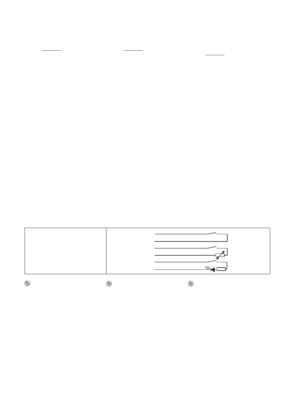
Anschlussbelegung
Terminal assignment
Affectation des broches
807841803
Der Sicherheitsschalter ist in unbetätigtem Zu-
stand dargestellt.
The safety switch is shown in an unoperated
condition.
Le capteur de sécurité est représenté en posi-
tion de repos.
Belegung des 6-adrigen Kabels/Layout of the
6-core cable/Repérage du câble à 6 conduc-
teurs
WICHTIG
Der Hilfskontakt mit LED
darf mit PNOZ X-Geräten nur mit Versor-
gungsspannung bis 24 V DC betrieben
werden
ist mit PNOZ X-, PNOZelog- und
PNOZmulti-Geräten nicht in Reihe
schaltbar
NOTICE
The auxiliary contact with LED
May only be operated with a supply volt-
age of up to 24 VDC with PNOZ X units
May not be connected in series with
PNOZ X, PNOZelog and PNOZmulti
units
IMPORTANT
Le contact d'information avec LED
ne doit être utilisé, pour les appareils
PNOZ X, qu'avec une alimentation jus-
qu'à 24 V DC
ne peut pas être monté en série avec les
appareils PNOZ X, PNOZelog et
PNOZmulti
R
lmax
- R
i
R
l
/ km
I
max
=
R
lmax
- R
i
R
l
/ km
I
max
=
R
lmax
- R
i
R
l
/ km
I
max
=
weiß/white/blanc
braun/brown/marron
blau/blue/bleu
schwarz/black/noir
rot/red/rouge
grün/green/vert
1
2
3
4
5+
6