Installation and operating instructions – Pilz PSENme 4.2 / 4A User Manual
Page 3
Installation and Operating Instructions
Date of issue: 31.01.2005 / Page 3 of 5
Document: 0800000424_en / Version: 1
Pilz GmbH & Co. KG, Sichere Automation, Felix-Wankel-Straße 2, D-73760 Ostfildern, Deutschland
Phone: +49 711 3409-0, Fax: +49 711 3409-133, E-Mail: [email protected], www.pilz.com
Template : 0850174292 Orig. 2
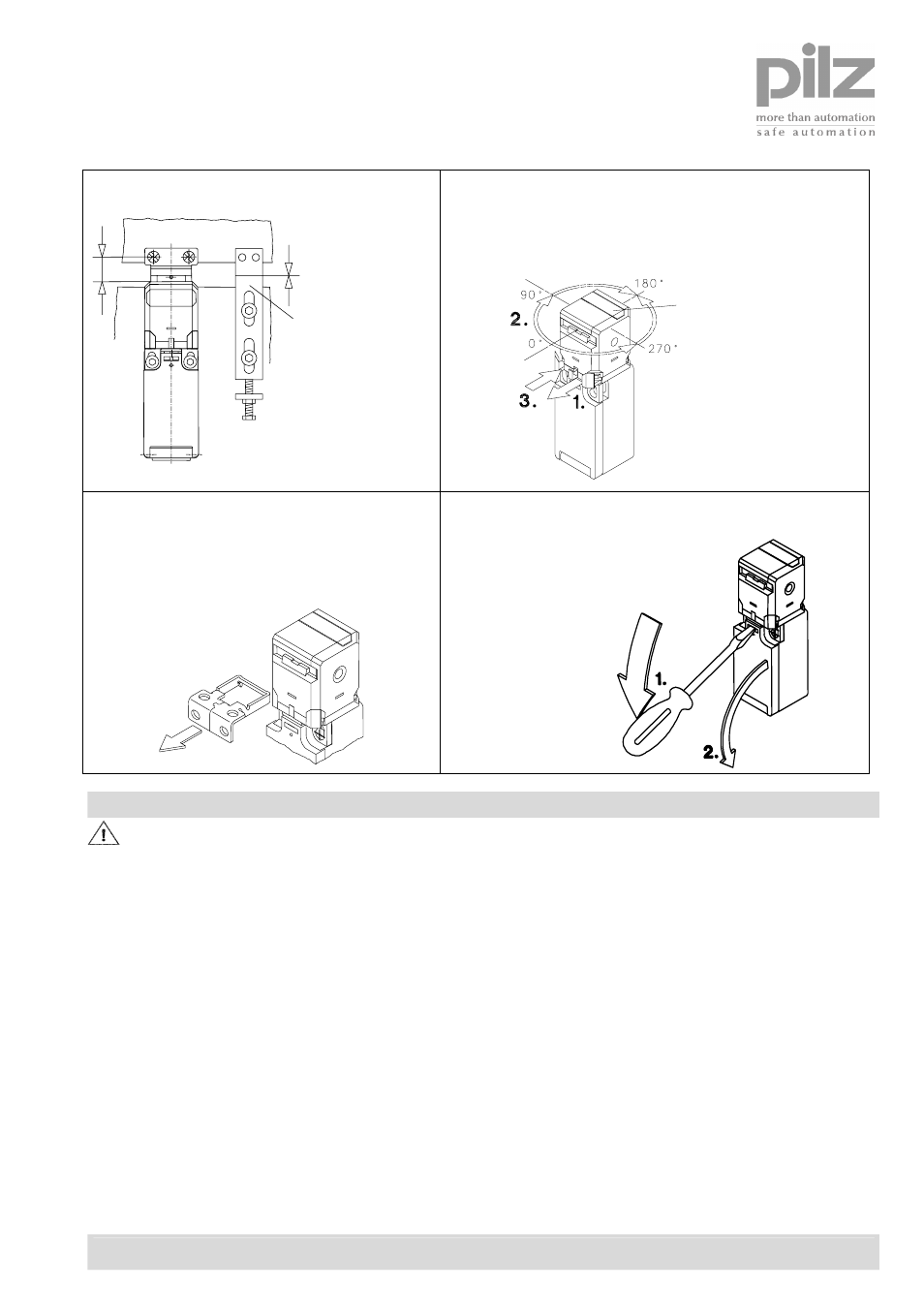
The safety switch shall not be used as
mechanical end stop!
Position of
mechanical stop adjustable
(not supplied with
safety switch)
4 different directions of actuation by turning the cap
from 0° to 270°:
1. draw clasp out
2. turn actuator head
3. press-on
clasp
Cover for unused entry
Actuating forces (Extraction force):
Standard = 10 N
PSEN me4.01, PSEN me4.11,
PSEN me4.21 = 50 N
Connecting the cable:
Connection type:
2 or 4 screw connectors M3,5 or
6 screw connectors M3
Conductor cross section:
single core 0,5-1,5 mm²/litz wire with
connector sleeve 0,5-1,5 mm²
Electrical connection
The electrical connection shall only be carried out by trained and qualified personnel!
The electrical contacts of switches PSEN me4, PSEN me4.01, PSEN me4.1 and PSEN me4.11 feature 4 screw
terminals M3,5.
Tightening torque M = 0,8 Nm.
The electrical contacts of switches PSEN me4.2 and PSEN me4.21 feature 6 screw terminals M3.
Tightening torque M = 0,6 Nm.
The connection requires a stranded wire with ferrule or a solid wire with a cross section of 0,5 – 1,5 mm².
For safety circuits acc. EN 60204 use the normally closed contact(s) (N.C.) only.