Start-up, Perform system, Check-out – Carrier 33ZCFANTRM User Manual
Page 29
29
START-UP
Use the Carrier network communication software to start up
and configure the zone controller.
All set-up and set point configurations are factory-set and
field-adjustable.
Changes can be made using the ComfortWORKS
®
soft-
ware, ComfortVIEW™ software, or Network Service Tool.
The Network Service Tool is a portable interface device that al-
lows the user to change system set-up and set points from a
zone sensor or terminal control module. During start-up, the
Carrier software can also be used to verify communication
with each zone controller.
For specific operating instructions, refer to the literature
provided with the software.
Perform System
Check-Out
1. Check correctness and tightness of all power and com-
munication connections.
2. Check that all air terminals, ductwork, and zone con-
trollers are properly installed and set according to
installation instructions and job requirements.
3. Check that all air duct connections are tight.
4. At the air terminals, check fan and system controls for
proper operation. Verify that actuator screws are prop-
erly tightened.
5. At the air terminals, check electrical system and con-
nections of any optional electric reheat coil. If hot
water reheat is used, check piping and valves against
job drawings.
6. At the air terminals, make sure that all balancing
dampers at box outlets are in the fully open position.
7. If using an air handler with field-installed controls,
make sure controls and sensors have been installed and
wired per manufacturer installation instructions.
8. At air handlers, verify that the motor starter and, if
applicable, the Hand/Off/Auto (HOA) switch are
installed and wired.
NOTE: The HOA switch must be in the Off position.
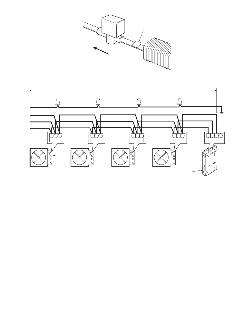
800
33ZCSENCHG
(SENSOR)
FLOW
1/2” TUBE
3/4” TUBE
1” TUBE
→ Fig. 24 — Typical Water Valve and Sensor Installation
CCN
1
2
3
CCN
1
2
3
CCN
1
2
3
AIR TERMINAL
UNIT (TYP)
CCN
1
2
3
COMM 2
1
2
3 4
GND
ZC
(TYP)
1000 FT. MAXIMUM
DRAIN WIRE (TYP)
BLK (TYP)
WHT (TYP)
RED (TYP)
BRIDGE
(RECOMMENDED)
LEGEND
Fig. 25 — Communication Bus Wiring
CCN
— Carrier Comfort Network
ZC
— Zone Controller