Smart Power Systems LR Series User Manual
Page 20
Smart Power
®
Systems
A. C. MODULAR GENERATOR SYSTEM
Page 19 of 49
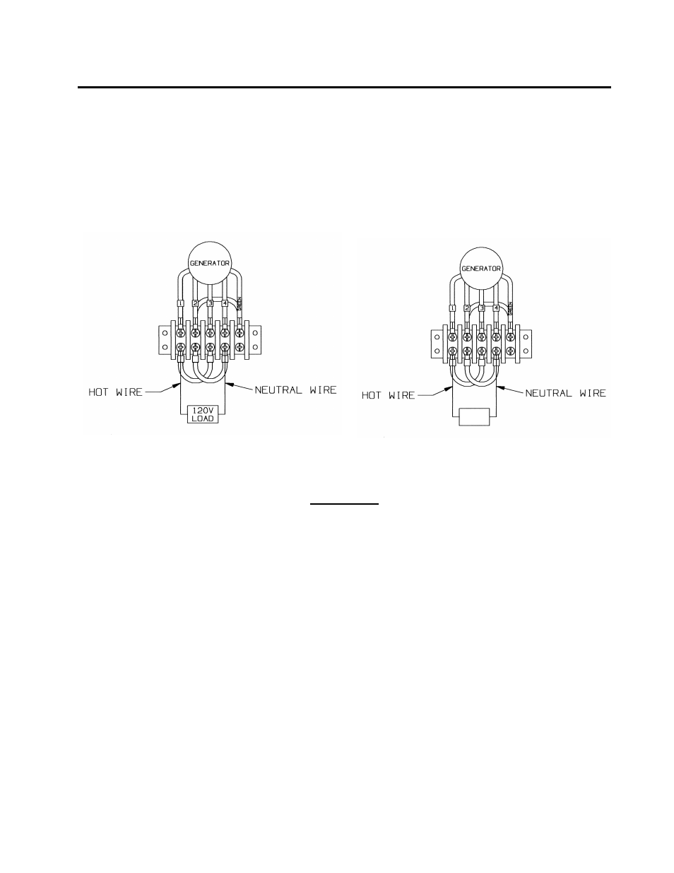
for 50 Hz system only, the generator terminal strip should be configured as depicted
below. This method ensures balanced loading of the generator, fully optimizing the
system’s capabilities. Make the following wire connections at the terminal strip:
a) place one jumper between wire 1 and wire 3.
b) place the second jumper between wire 2 and wire 4.
c) connect the phase wire from the breaker box to either wire 1 or wire 3.
d) connect the neutral wire from the breaker box to either wire 2 or wire 4.
e) connect the ground wire from the breaker box to the green wire.
60 Hz 50 Hz
WARNING:
To ensure proper voltage regulation, during the operation of generator system, the
load difference between Phase A and Phase B must never exceed 20%. Damage to
generator system caused by operating it with an unbalanced load will void the
system’s warranty.
Wiring of the A.C. modular generator system and electrical distribution throughout
the vehicle must be done in accordance with applicable sections in the National Fire
Protection Association’s document NFPA 1901, the National Electrical Code
®
and/or
other applicable, recognized electrical code and by a certified electrician.
Smart Power
®
Systems’ A.C. modular generators are supplied with the neutral
bonded to ground. Refer to National Fire Protection Association’s document NFPA
1901, National Electrical Code
, and/or other applicable recognized electrical codes
before wiring an SPS A.C. modular generator system.
Never wire any loads to the generator’s output without a circuit breaker in series
with the load. Damage to the generator, to the components within that circuit,
electrical shock, or fire may result if a short occurs in an unprotected circuit. Run
all 120 VAC and 240 VAC electrical connections between the generator and the
distribution panel in conduit. Bypassing the SPS factory installed breaker will void
110V
LOAD