3 setting the digital filter parameters, 8 analog output calibration, Setting the digital filter parameters – Rice Lake SURVIVOR 420HE Hostile Environment - Installation Manual User Manual
Page 50: Figure 7.8 46 for an
46
420HE Installation Manual
7.7.3
Setting the Digital Filter Parameters
Fine-tuning the digital filter parameters greatly
improves indicator performance in heavy-vibration
environments. Use the following procedure to
determine vibration effects on the scale and optimize
the digital filtering configuration.
1. In setup mode, set all three digital filters
( D I G F L 1 , D I G F L 2 , D I G F L 3 ) t o 1 . S e t
DFTHRH to NONE. Return indicator to
normal mode.
2. Remove all weight from the scale, then watch
t h e i n d i c a t o r d i s p l a y t o d e t e r m i n e t h e
magnitude of vibration effects on the scale.
Record the weight below which all but a few
readings fall. This value is used to calculate the
DFTHRH parameter value in Step 4.
For example, if a heavy-capacity scale
produces vibration-related readings of up to 50
lb, with occasional spikes to 75 lb, record 50 lb
as the threshold weight value.
3. Place the indicator in setup mode and set the
digital filters (DIGFLx) to eliminate the
v i b r a t i o n e ff e c t s o n t h e s c a l e . ( L e a v e
DFTHRH set to NONE.) Reconfigure as
necessary to find the lowest effective values
for the DIGFLx parameters.
4. With optimum values assigned to the DIGFLx
parameters, calculate the DFTHRH parameter
value by converting the weight value recorded
in Step 2 to display divisions:
threshold_weight_value / DSPDIV
In the example in Step 2, with a threshold
weight value of 50 lb and a display division
value of 5lb:
50 / 5lb = 10DD.
DFTHRH should
be set to 10DD for this example.
5. Finally, set the DFSENS parameter high
enough to ignore transient peaks. Longer
transients (typically caused by lower vibration
frequencies) will cause more consecutive
out-of-band readings, so DFSENS should be
set higher to counter low frequency transients.
Reconfigure as necessary to find the lowest
effective value for the DFSENS parameter.
7.8
Analog Output Calibration
The following calibration procedure requires a multimeter to measure voltage or current output from the analog
output module. If the option is not already installed, see Section 2.3.5 on page 8.
XXXXXXX
XXXXXXX
ALGOUT
DIGIN
SETPNT
XXXXXXX
PROGRM
PFORMT
SERIAL
CALIBR
XXXXXXX
CONFIG
FORMAT
SOURCE
GROSS
0%
20%
OFFSET
ERRACT
FULLSC
HOLD
000000
number
MIN
10000
number
MAX
TWZERO
NET
ZEROSC
VERS
MINNEG
OFF
ON
MAXNEG
OFF
ON
Note
The analog output must be calibrated after the indicator itself has been configured (Section 3.0) and
calibrated (Section 4.0).
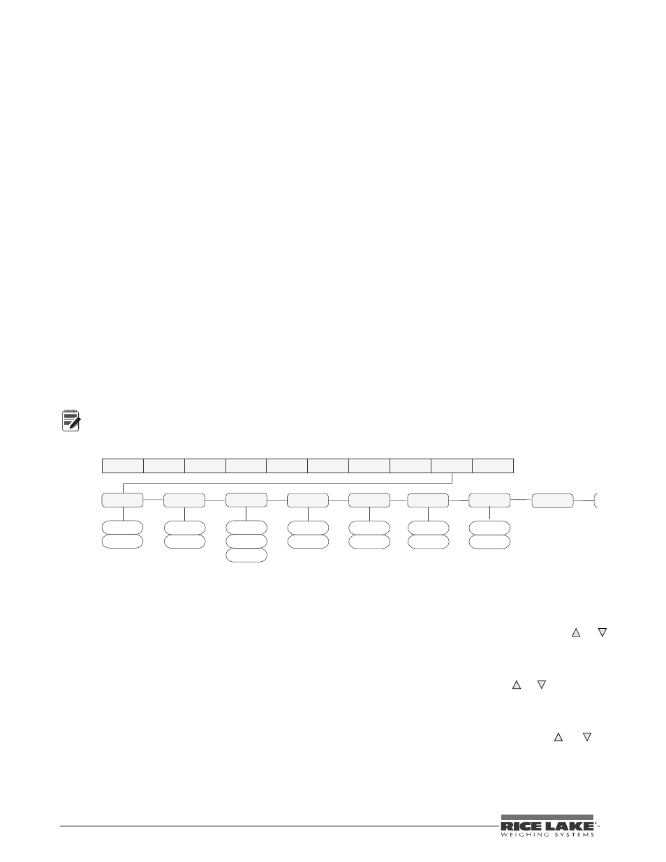
Figure 7-5. Analog Output Menu
1. Enter setup mode and go to the ALGOUT
menu (see Figure 7-5).
•
Set OFFSET to 0% for 0–10 V output,
20% for 4–20 mA output
•
Set MIN to lowest weight value to be
tracked by the analog output
•
Set MAX to highest weight value to be
tracked by the analog output
2. Connect multimeter to analog output:
•
For voltage output, connect voltmeter
leads to pins three and four
•
For current output, connect ammeter leads
to pins one and two
3. Adjust zero calibration: Scroll to the
TWZERO parameter. Check voltage or current
reading on multimeter. Press and hold or
to adjust the zero value up or down.
4. Adjust span calibration: Scroll to the TWSPAN
parameter. Check voltage or current reading on
multimeter. Press and hold or to adjust the
span value up or down.
5. Final zero calibration: Return to the TWZERO
parameter and verify that the zero calibration
has not drifted. Press and hold or to
re-adjust the zero value as required.
6. Return to normal mode. Analog output
function can be verified using test weights.