Trigger jack connector pins, Location and positioning, Trigger jack connector pins -10 – Rice Lake Motorola DS457 Laser Scanner User Manual
Page 34: Location and positioning -10, Serial interface cable, Figure 2-10, Serial interface cable connection, Ttl level compatible rs-232 host systems, Host systems which require true rs-232 levels
2 - 10 DS457 Fixed Mount Imager Integration Guide
Serial Interface Cable Connection
When connecting via RS-232, identify the type of host system to determine the cable needed. If you are unsure
what host system you are using, contact the local Motorola Solutions representative.
TTL Level Compatible RS-232 Host Systems
If using a PC, laptop, or POS terminal, the host system most likely has an RS-232 port which is compatible with
TTL levels. In this case, use the standard 5V RS-232 cable.
Host Systems Which Require True RS-232 Levels
Some host devices are not compatible with TTL level signals and require true RS-232 levels, such as those in
electrically noisy environments and locations with long cable runs. In such installations the DS457 may require
a level-shifting cable, such as p/n 25-62186-03R, to interface to this host system.
Failure to use the appropriate cable can impact the imager’s ability to reliably communicate with the host under
some conditions.
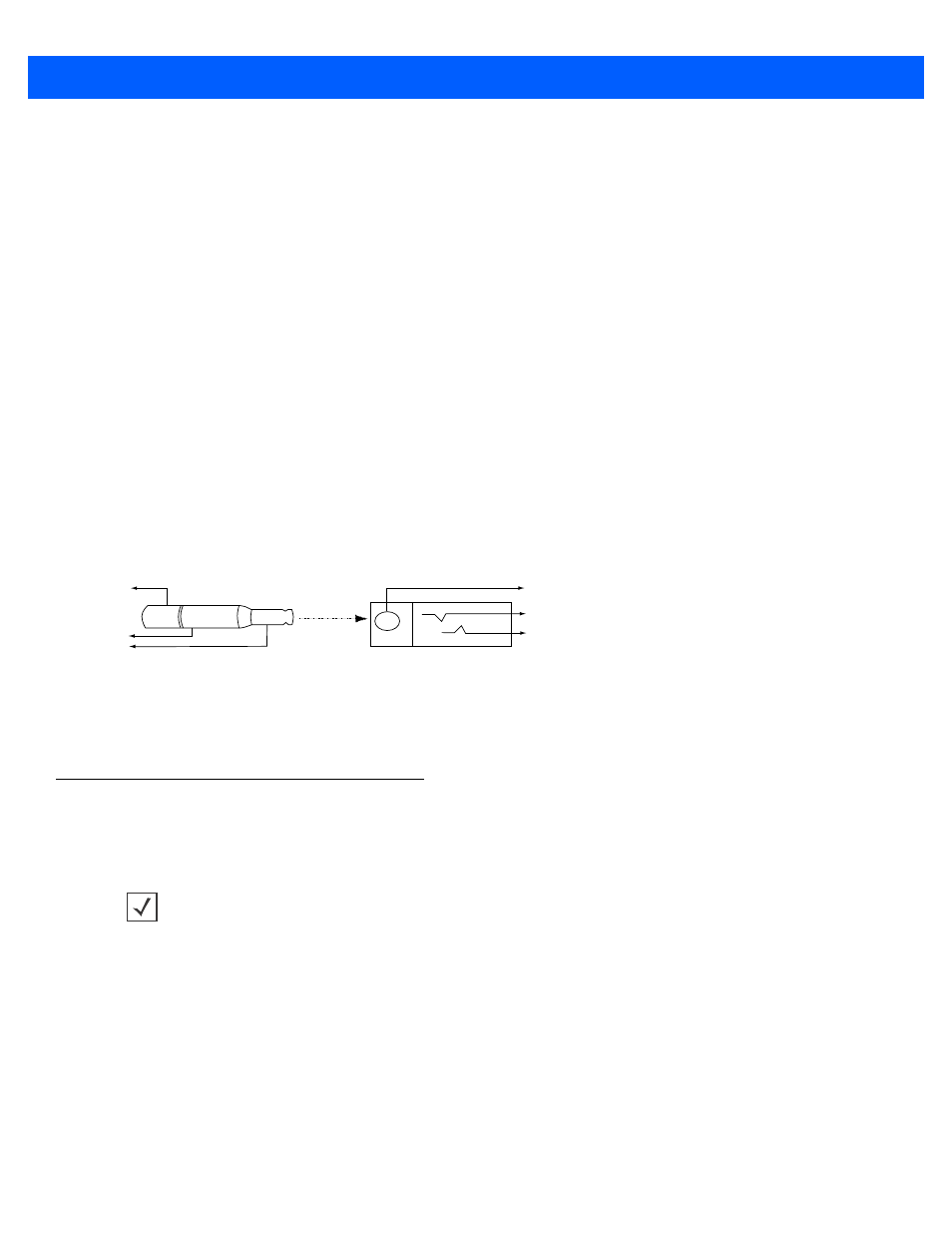
Trigger Jack Connector Pins
Figure 2-10
Trigger Jack Connector Pins
Location and Positioning
The location and positioning guidelines do not consider unique application characteristics. Motorola
recommends that an opto-mechanical engineer perform an opto-mechanical analysis prior to integration.
Male jack shown for reference
Note: Due to many variations of
jack and socket styles, identify
terminals as shown before
soldering leads.
1
1
2
2
3
3
Insertion
Direction
1 - Ground (Sleeve)
2 - Battery (Middle Contact)
3 - Trigger (Tip)
1 - Ground (Sleeve)
2 - Vcc (Middle Contact)
3 - Trigger (Tip)
NOTE
Integrate the imager in an environment no more extreme than the product’s specification, where the
imager will not exceed its temperature range. For instance, do not mount the imager onto or next to a large
heat source. When placing the imager with another device, ensure there is proper convection or venting
for heat. Follow these suggestions to ensure product longevity, warranty, and overall satisfaction with the
imager.