4 digital i/o, 4 installing option cards, Digital i/o – Rice Lake 920i Installation Manual V1.05 User Manual
Page 13: Caution j5 j6
Installation
9
2.3.4
Digital I/O
Digital inputs can be set to provide many indicator
functions, including all keypad functions. Digital
inputs are active low (0 VDC), inactive high (5 VDC).
Digital outputs are typically used to control relays that
drive other equipment. Outputs are designed to sink,
rather than source, switching current. Each output is a
normally open collector circuit, capable of sinking 24
mA when active. Digital outputs are wired to switch
relays when the digital output is active (low, 0 VDC)
with reference to a 5 VDC supply.
Table 2-4 shows the pin assignments for connector J2.
Digital inputs and outputs are conÞgured using the
DIG I/O menu. See Section 3.2.6 on page 37 for
conÞguration information.
An optional 24-channel digital I/O expansion card,
PN 67601, is available for applications requiring more
digital I/O channels.
2.4
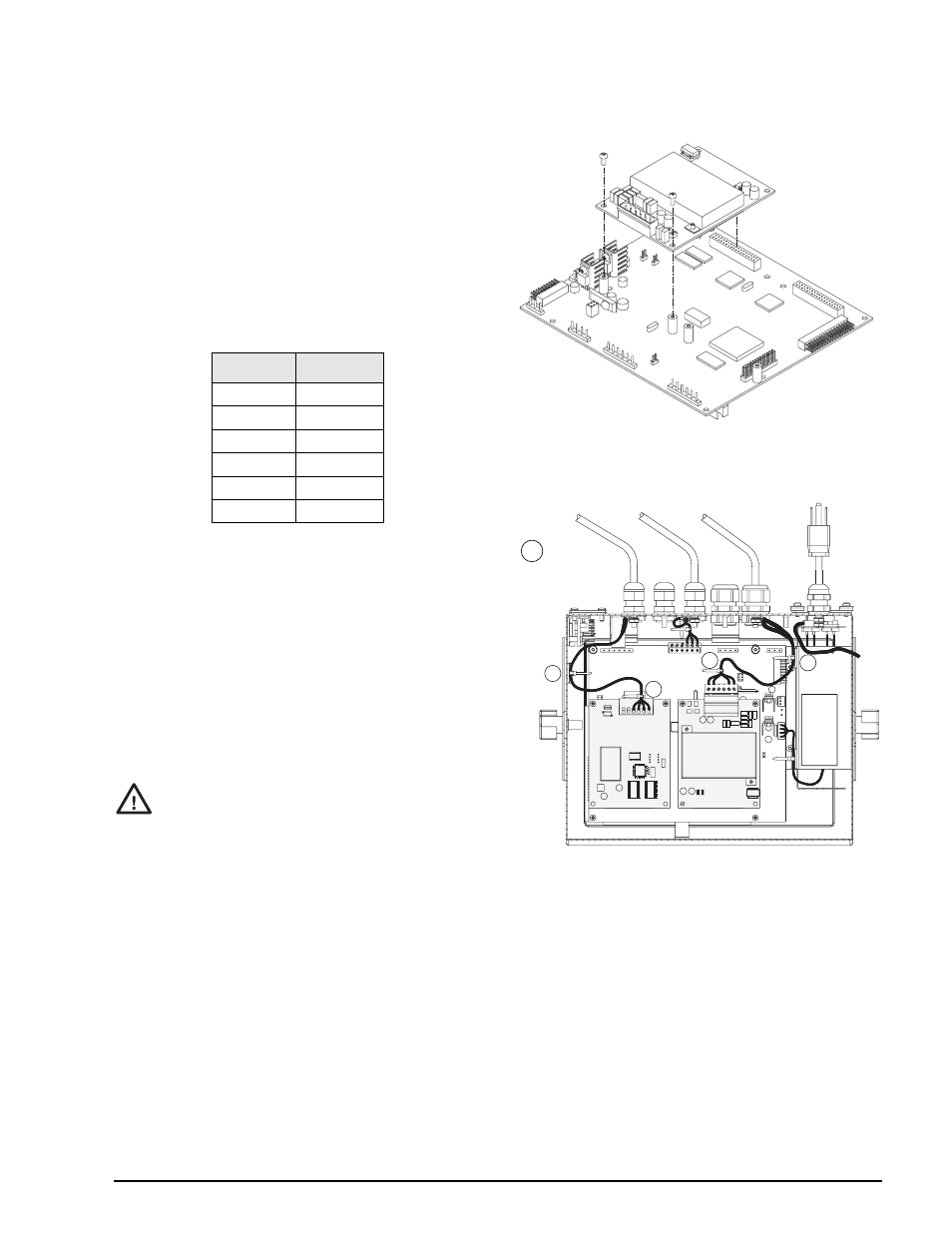
Installing Option Cards
Each option card is shipped with installation
instructions speciÞc to that card. The general
procedure for all option cards is as follows:
Option cards are not hot-pluggable.
Disconnect power to the
920i
before
installing option cards.
1. Disconnect power to the indicator. Remove
backplate as described in Section 2.2 on page 6.
2. Carefully align the large option card connector
with connector J5 or J6 on the CPU board (see
Figure 2-5). Press down to seat the option card
in the CPU board connector.
3. Use the screws provided in the option kit to
secure the other end of the option card to the
threaded standoffs on the CPU board (see
Figure 2-5).
4. Make connections to the option card as required.
Use cable ties to secure loose cables inside the
enclosure as shown in Figure 2-6. When
i n s t a l l a t i o n i s c o m p l e t e , r e a s s e m b l e t h e
enclosure as described in Section 2.6 on
page 11.
Figure 2-5. Installing Option Card Onto CPU Board
Figure 2-6. Installed Option Cards, Showing Secured
Cables
The
920i
automatically recognizes all installed option
c a r d s w h e n t h e u n i t i s p o w e r e d o n . N o
hardware-speciÞc conÞguration is required to identify
the newly-installed card to the system.
J2 Pin
J2 Signal
1
+5 VDC
2
GND
3
DIO 1
4
DIO 2
5
DIO 3
6
DIO 4
Table 2-4. J2 Pin Assignments (Digital I/O)
Caution
J5
J6
W
ARNING!
HIGH VOL
TAGE
DISCONNECT POWER BEFORE SER
VICING
PULSE INPUT
CARD
DUAL A/D
CARD
INDICATES
OPTION CARD
CABLE TIES
CT
CT
CT
CT
CT