36 splice – Oldcastle BuildingEnvelope Reliance-TC User Manual
Page 36
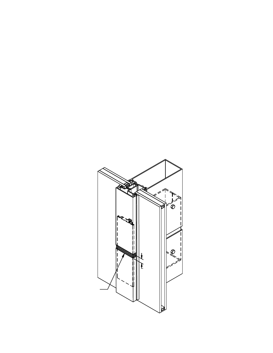
FIGURE 36
Sealing Splice Joint
Type I Verticals
Install backer rod
and seal between
mullions.
1/2"
Refer to MULTI-SPAN INSTALLATION, page 14 for splice sleeve installation.
Follow sealant manufacturer's guidelines for proper joint width based on anticipated movement. A minimum ½”
joint is recommended. Note: Standard splice joints are engineered to accommodate thermal expansion
only. They do not allow for movement in floor levels. Refer to approved shop drawings for special
circumstances, or contact your nearest Oldcastle BuildingEnvelope facility.
B.1 Apply bond breaker tape to the face of splice sleeves, returning back on the sides 1” minimum. Insert
backer rod into the hollow of the vertical mullion, top and bottom. Seal between top and bottom mullion
from the front of the tongue to 1” behind glass pocket. Follow the contour of the glazing reglets with the
sealant to insure a good seal when gaskets are installed. SEE FIGURE 9, page 14.
B.2 Discontinue glazing adaptors at splice joints. Install backer rod into cavity and seal between adaptors.
Marry adaptor seal with main mullion seal. Refer to step B.1 above for sealing notes at glazing reglets.
B.3 Seal face of WW-520 and similar verticals by installing backer rod in joint and seal per FIGURE 36.
B.4 Offset pressure plates and face covers per FIGURE 37 page 37, sealing pressure plate and face cover
joints as shown in FIGURE 38, page 37.
VERTICAL SPLICING
R E L I A N C E - T C C U R T A I N W A L L I N S T A L L A T I O N M A N U A L
TM
MAY 2013
36
Phone: 1-866-OLDCASTLE (653-2278)
Web Address: www.oldcastlebe.com
®
®