Standard interfaces – pin assignments, Serial interfaces com 1 and com 2 (rs232), Dp connector (displayport) – Kontron KBox B-101 Configuration Guide User Manual
Page 38
13. Standard Interfaces – Pin Assignments
KBox B-101 – User’s Guide (Version 1.00)
13.
Standard Interfaces – Pin Assignments
Low-active signals are indicated by a minus sign.
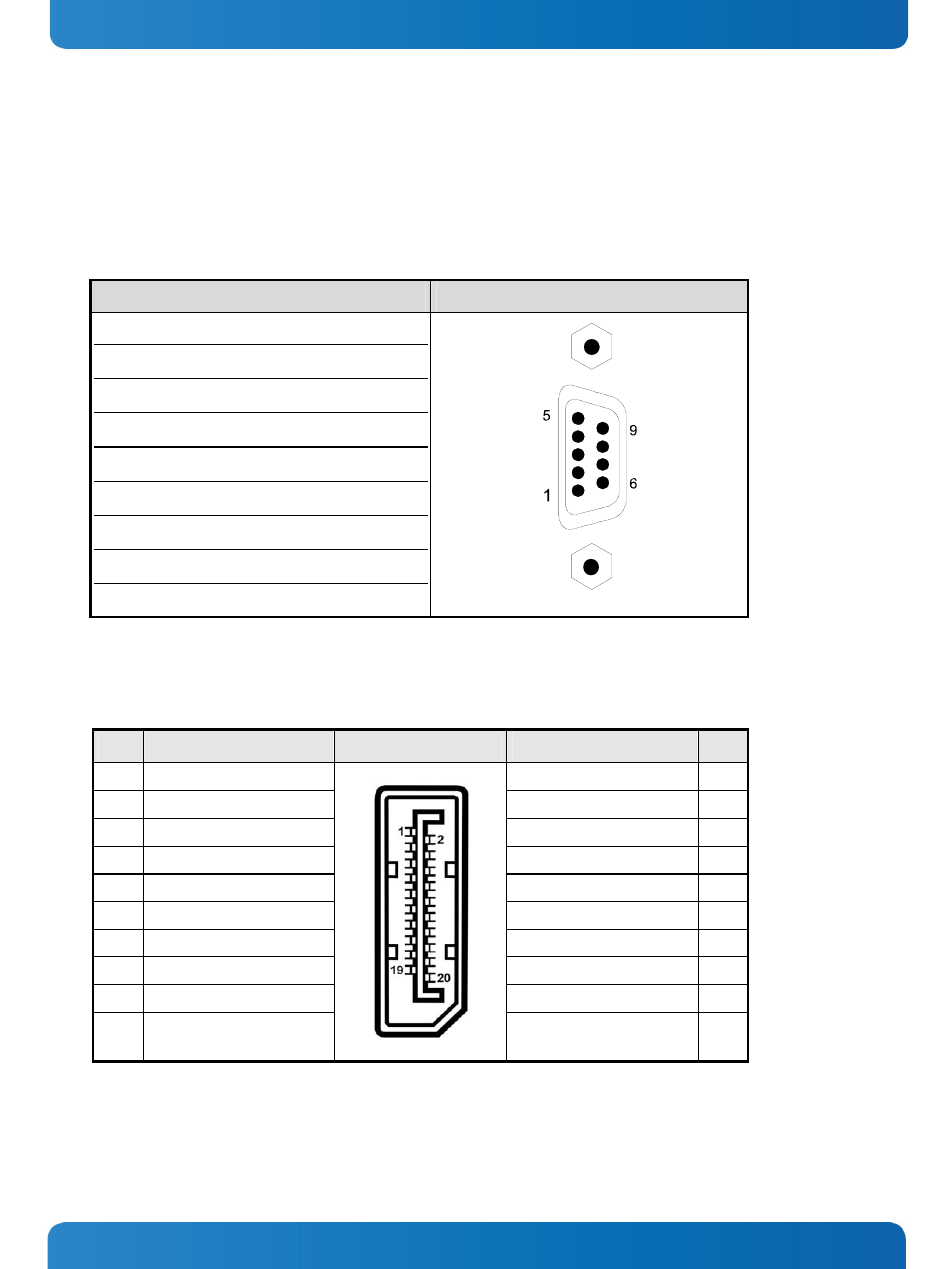
13.1.1. Serial Interfaces COM 1 and COM 2 (RS232)
Pin Signal
Name
9-pin D-SUB Connector
1
DCD
(Data Carrier Detect)
2 RXD (Receive
Data)
3 TXD (Transmit
Data)
4
DTR
(Data Terminal Ready)
5 GND (Signal
Ground)
6
DSR
(Data Set Ready)
7
RTS
(Request to Send)
8
CTS
(Clear to Send)
9 RI (Ring
Indicator)
13.1.2. DP Connector (DisplayPort)
Pin# Signal Name
DisplayPort
Signal Name
Pin#
1
ML Lane 0 (p)
GND (ML Lane 0)
2
3
ML Lane 0 (n)
Lane 1 (p)
4
5
GND (ML Lane 1)
Lane 1 (n)
6
7
Lane 2 (p)
GND (ML Lane 2)
8
9
Lane 2 (n)
Lane 3 (p)
10
11
GND (ML Lane 3)
Lane 3 (n)
12
13
AUX SEL#
Pull-down to GND
14
15
AUX CH (p)
GND (AUX CH)
16
17
AUX CH (n)
Hot Plug
18
19 GND
(GND_DDC)
3.3V (DDC EEPROM power
500 mA fused
20
36
www.kontron.com