Aa. bp usb 0/1 wake-up b. bmc enable, X9scm/x9scl(-f) – Kontron X9SCL+-F User Manual
Page 60
2-34
X9SCM/X9SCM-F/X9SCL/X9SCL-F/X9SCL+-F User's Manual
J31
JTPM
J29
JL1
JI2C2
JI2C1
T-SGPIO1
JWF1
JPW2
JWOL
JSPK
JPI2C
JPW1
COM1
SPKR1
JBT1
LE2
JWD
JLED1
JPL2
JPG1
JPB
JPL1
JPUSB1
FAN1
FANA
FAN3
FAN2
DDR3 1066/1333 UDIMM required
USB4/5
USB 12/13
_LAN
IPMI
COM2
VGA
USB11
DIMM2B
DIMM2A
USB2/3
Slot6 PCI-E 2.0 x8
JF1
I-SA
TA2
Slot4 PCI-E 2.0 x4 on x8
KB/MOUSE
DIMM1B
DIMM1A
CPU
Slot7 PCI-E 2.0 x8
BIOS
B1
Battery
PHY
BMC
CTRL
82574L
S I/O
T-SGPIO2
FP CTRL
Cougar Point
Standard PCH
Memory Chip
X9SCM/X9SCL(-F)
Rev.1.0
Fan4
PHY
82579
PHY
(For X9SCM only)
(*I-SATA 0/1:
X9SCL: SATA2, X9SCM: SATA3)
Socket H2
LGA 1155
CPU
I-SA
TA4
I-SA
TA5
I-SA
TA3
I-SA
TA1
I-SA
TA0
Slot5 PCI-E 2.0 x4 on x8
USB/0/1
LAN1
LAN2
LE7
JPME1
JPME2
LE4
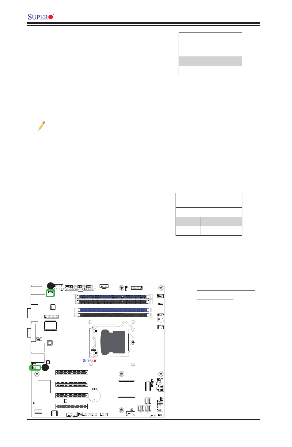
A
A. BP USB 0/1 Wake-up
B. BMC Enable
USB Wake-Up
Use the jumper JPUSB1 to "wake-up" your
system by pressing a key on a USB keyboard
or clicking the USB mouse connected to the
Backplane USB Ports 0/1. JPUSB1 is used
together with a USB Wake-Up feature in the
BIOS. Enable this jumper and the USB sup-
port in the BIOS to wake up your system via
USB devices.
Note: When the USB is set to Enabled in
the BIOS, and JPUSB1 is set to Disabled,
remove the USB devices from Backplane
USB Ports 0/1 before the system goes
into the standby mode.
JPUSB1 (Backplane USB
0/1 Wake-up Enable)
Pin# Definition
1-2
Enabled (Default)
2-3
Disabled
B
BMC Enable
JPB is used to enable or disable the BMC
(Baseboard Management Control) chip and
the onboard IPMI connection. This jumper is
used together with the IPMI settings in the
BIOS. See the table on the right for jumper
settings.
BMC IPMI Enable/Disable
Jumper Settings
Settings Definition
Pins 1-2
Enabled (Default)
Pins 2-3
Disabled