Ab a.dom pwr b. wol – Kontron X9SCL+-F User Manual
Page 56
2-30
X9SCM/X9SCM-F/X9SCL/X9SCL-F/X9SCL+-F User's Manual
J31
JTPM
J29
JL1
JI2C2
JI2C1
T-SGPIO1
JWF1
JPW2
JWOL
JSPK
JPI2C
JPW1
COM1
SPKR1
JBT1
LE2
JWD
JLED1
JPL2
JPG1
JPB
JPL1
JPUSB1
FAN1
FANA
FAN3
FAN2
DDR3 1066/1333 UDIMM required
USB4/5
USB 12/13
_LAN
IPMI
COM2
VGA
USB11
DIMM2B
DIMM2A
USB2/3
Slot6 PCI-E 2.0 x8
JF1
I-SA
TA2
Slot4 PCI-E 2.0 x4 on x8
KB/MOUSE
DIMM1B
DIMM1A
CPU
Slot7 PCI-E 2.0 x8
BIOS
B1
Battery
PHY
BMC
CTRL
82574L
S I/O
T-SGPIO2
FP CTRL
Cougar Point
Standard PCH
Memory Chip
X9SCM/X9SCL(-F)
Rev.1.0
Fan4
PHY
82579
PHY
(For X9SCM only)
(*I-SATA 0/1:
X9SCL: SATA2, X9SCM: SATA3)
Socket H2
LGA 1155
CPU
I-SA
TA4
I-SA
TA5
I-SA
TA3
I-SA
TA1
I-SA
TA0
Slot5 PCI-E 2.0 x4 on x8
USB/0/1
LAN1
LAN2
LE7
JPME1
JPME2
LE4
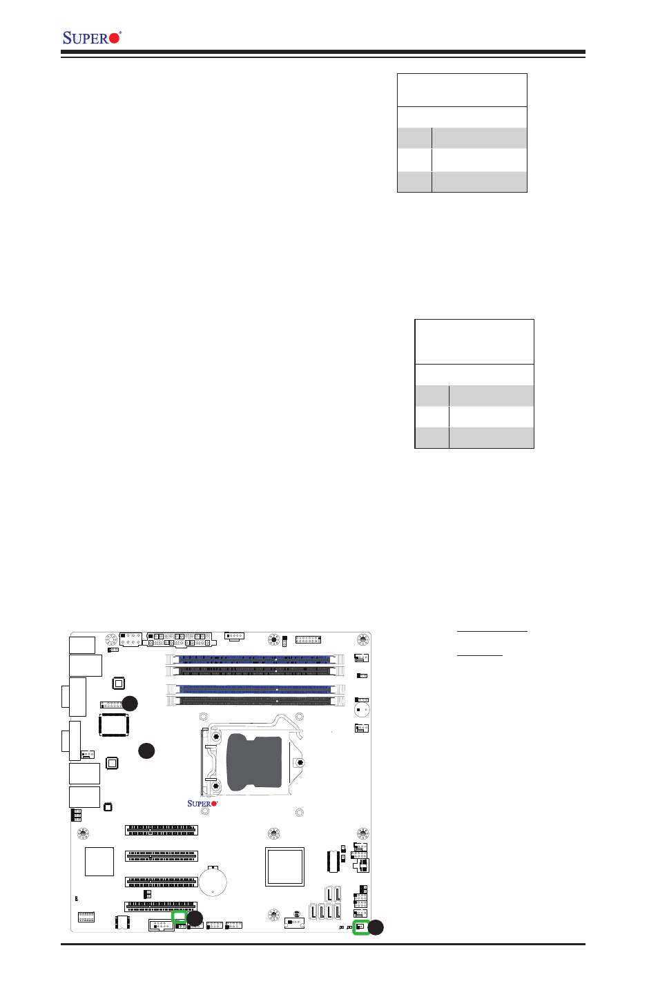
A
B
DOM PWR Connector
The Disk-On-Module (DOM) power
connector, located at JWF1, provides
5V (Gen1/Gen) power to a solid_state
DOM storage device connected to one
of the SATA ports. See the table on the
right for pin definitions.
DOM PWR
Pin Definitions
Pin# Definition
1
5V
2
Ground
3
Ground
Wake-On-LAN
The Wake-On-LAN header is located
at JWOL on the motherboard. See the
table on the right for pin definitions.
(You must also have a LAN card with
a Wake-On-LAN connector and cable
to use this feature.)
Wake-On-LAN
Pin Definitions
(JWOL)
Pin# Definition
1
+5V Standby
2
Ground
3
Wake-up
A
B
A.DOM PWR
B. WOL