7 jumper settings, Explanation of jumpers, Chapter 2: installation – Kontron X9SCL+-F User Manual
Page 57: A. lan port 1 enable b. lan port 2 enable, Ab a b, X9scm/x9scl(-f)
Chapter 2: Installation
2-31
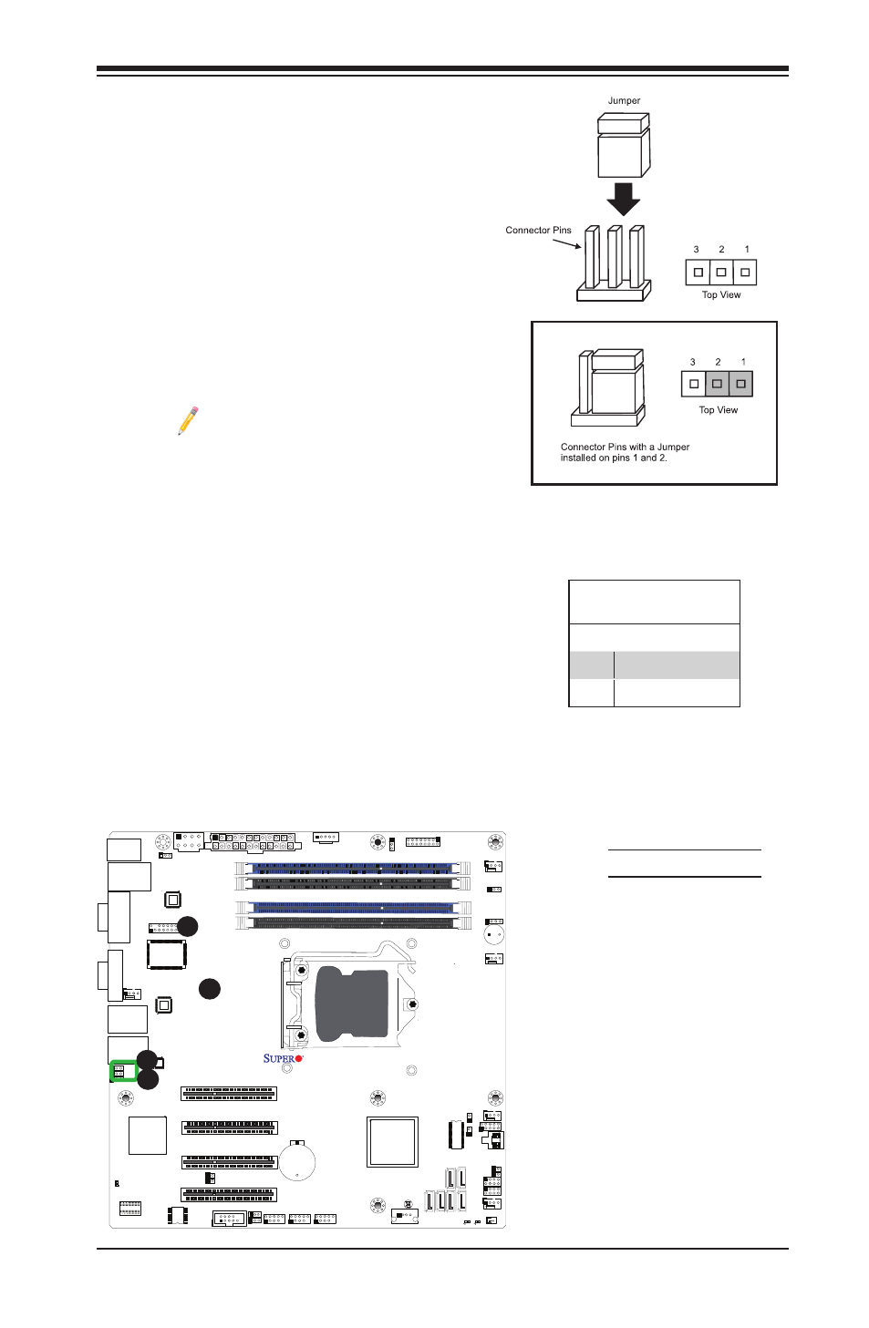
2-7 Jumper Settings
Explanation of Jumpers
To modify the operation of the mother-
board, jumpers can be used to choose
between optional settings. Jumpers create
shorts between two pins to change the
function of the connector. Pin 1 is identified
with a square solder pad on the printed
circuit board.
Note: On two pin jumpers,
"Closed" means the jumper is on,
and "Open" means the jumper is
off the pins.
A. LAN Port 1 Enable
B. LAN Port 2 Enable
LAN Port Enable/Disable
Jumpers JPL1/JPL2 enable or disable
LAN Port 1/LAN Port 2 on the moth-
erboard. See the table on the right for
jumper settings. The default setting is
enabled.
GLAN Enable
Jumper Settings
Pin# Definition
1-2
Enabled (default)
2-3
Disabled
J31
JTPM
J29
JL1
JI2C2
JI2C1
T-SGPIO1
JWF1
JPW2
JWOL
JSPK
JPI2C
JPW1
COM1
SPKR1
JBT1
LE2
JWD
JLED1
JPL2
JPG1
JPB
JPL1
JPUSB1
FAN1
FANA
FAN3
FAN2
DDR3 1066/1333 UDIMM required
USB4/5
USB 12/13
_LAN
IPMI
COM2
VGA
USB11
DIMM2B
DIMM2A
USB2/3
Slot6 PCI-E 2.0 x8
JF1
I-SA
TA2
Slot4 PCI-E 2.0 x4 on x8
KB/MOUSE
DIMM1B
DIMM1A
CPU
Slot7 PCI-E 2.0 x8
BIOS
B1
Battery
PHY
BMC
CTRL
82574L
S I/O
T-SGPIO2
FP CTRL
Cougar Point
Standard PCH
Memory Chip
X9SCM/X9SCL(-F)
Rev.1.0
Fan4
PHY
82579
PHY
(For X9SCM only)
(*I-SATA 0/1:
X9SCL: SATA2, X9SCM: SATA3)
Socket H2
LGA 1155
CPU
I-SA
TA4
I-SA
TA5
I-SA
TA3
I-SA
TA1
I-SA
TA0
Slot5 PCI-E 2.0 x4 on x8
USB/0/1
LAN1
LAN2
LE7
JPME1
JPME2
LE4
A
B
A
B