6 connecting cables, Chapter 2: installation, Pin main pwr – Kontron X9SCL+-F User Manual
Page 51: A. 24-pin atx main pwr b. 8-pin processor pwr a b, Required)
Chapter 2: Installation
2-25
J31
JTPM
J29
JL1
JI2C2
JI2C1
T-SGPIO1
JWF1
JPW2
JWOL
JSPK
JPI2C
JPW1
COM1
SPKR1
JBT1
LE2
JWD
JLED1
JPL2
JPG1
JPB
JPL1
JPUSB1
FAN1
FANA
FAN3
FAN2
DDR3 1066/1333 UDIMM required
USB4/5
USB 12/13
_LAN
IPMI
COM2
VGA
USB11
DIMM2B
DIMM2A
USB2/3
Slot6 PCI-E 2.0 x8
JF1
I-SA
TA2
Slot4 PCI-E 2.0 x4 on x8
KB/MOUSE
DIMM1B
DIMM1A
CPU
Slot7 PCI-E 2.0 x8
BIOS
B1
Battery
PHY
BMC
CTRL
82574L
S I/O
T-SGPIO2
FP CTRL
Cougar Point
Standard PCH
Memory Chip
X9SCM/X9SCL(-F)
Rev.1.0
Fan4
PHY
82579
PHY
(For X9SCM only)
(*I-SATA 0/1:
X9SCL: SATA2, X9SCM: SATA3)
Socket H2
LGA 1155
CPU
I-SA
TA4
I-SA
TA5
I-SA
TA3
I-SA
TA1
I-SA
TA0
Slot5 PCI-E 2.0 x4 on x8
USB/0/1
LAN1
LAN2
LE7
JPME1
JPME2
LE4
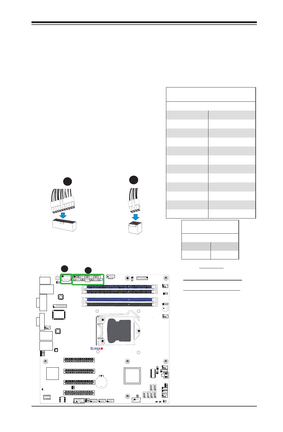
2-6 Connecting Cables
This section provides brief descriptions and pin-out definitions for onboard headers
and connectors. Be sure to use the correct cable for each header or connector. For
information on Backpanel USB and Front Panel USB ports, refer to Page 2-17. For
COM Port 1 and COM Port 2, please see Page 2-19.
A. 24-Pin ATX Main PWR
B. 8-Pin Processor PWR
A
B
ATX Power 24-pin Connector
Pin Definitions (JPW1)
Pin# Definition Pin # Definition
13
+3.3V
1
+3.3V
14
-12V
2
+3.3V
15
COM
3
COM
16
PS_ON
4
+5V
17
COM
5
COM
18
COM
6
+5V
19
COM
7
COM
20
Res (NC)
8
PWR_OK
21
+5V
9
5VSB
22
+5V
10
+12V
23
+5V
11
+12V
24
COM
12
+3.3V
(Required)
12V 8-pin Power Connec-
tor Pin Definitions
Pins Definition
1 through 4
Ground
5 through 8
+12V
ATX Main PWR & CPU PWR
Connectors
The 24-pin main power connector
(JPW1) is used to provide power to
the motherboard. The 8-pin CPU PWR
connector (JPW2) is also required for
the processor. These power connectors
meet the SSI EPS 12V specification. See
the table on the right for pin definitions.
8-Pin Processor PWR
A
B
24-Pin Main PWR