Kontron X9SCL+-F User Manual
Page 50
2-24
X9SCM/X9SCM-F/X9SCL/X9SCL-F/X9SCL+-F User's Manual
Power Button
The Power Button connection is located
on pins1 and 2 of JF1. Momentarily con-
tacting both pins will power on/off the sys-
tem. This button can also be configured
to function as a suspend button (with a
setting in the BIOS - see Chapter 4). To
turn off the power in the suspend mode,
press the button for at least 4 seconds.
Refer to the table on the right for pin
definitions.
Power Button
Pin Definitions (JF1)
Pin# Definition
1
Signal
2
Ground
Reset Button
The Reset Button connection is located
on pins 3 and 4 of JF1. Attach it to a
hardware reset switch on the computer
case to reset the system. Refer to the
table on the right for pin definitions.
Reset Button
Pin Definitions (JF1)
Pin# Definition
3
Reset
4
Ground
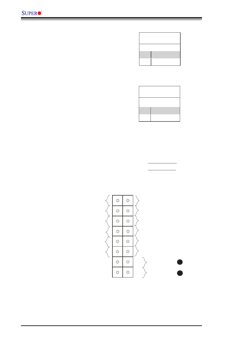
A. Reset Button
B. PWR Button
A
B
Power Button
OH/Fan Fail LED
1
NIC1 LED
Reset Button
2
HDD LED
Power LED
Reset
PWR
LED_Anode+
LED_Anode+
LED_Anode+
UID LED
Ground
Ground
Power Fail LED
NIC2 LED
LED_Anode+
LED_Anode+