Pinout feature connector j9, 5 pinout feature connector j9 – Kontron ETX-DC User Manual
Page 38
ETX-DC®/ ETX® Connectors
33
When you have as boot display device SDVO enabled and you have installed a windows operating system then after the
graphic driver installation your SDVO interface is disabled. You can enable it in blind mode by pressing the key
combination
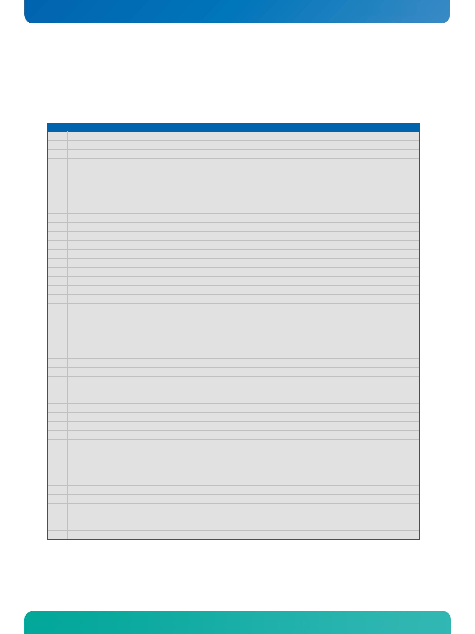
4.8.5 Pinout Feature Connector J9
Pin Pin on ETX®-CD
Description
1
GND1
Ground
2
SDVOC_CLKN
nc
3
SDVOC_CLKN
nc
4
GND2
Ground
5
SDVOC_GREENN
nc
6
SDVOC_GREENP
nc
7
GND3
Ground
8
SDVOB_CLKN
Channel B; Clock negative
9
SDVOB_CLKN
Channel B; Clock positive
10
GND4
Ground
11
SDVOB_GREENN
Channel B; Green negative
12
SDVOB_GREENP
Channel B; Green positive
13
GND5
Ground
14
SDVOC_INTN
nc
15
SDVOC_INTP
nc
16
GND6
Ground
17
SDVOB_INTN
Channel B; Interrupt negative
18
SDVOB_INTP
Channel B; Interrupt positive
19
GND7
Ground
20
SDVOC_BLUEN
nc
21
SDVOC_BLUEP
nc
22
GND8
Ground
23
SDVOC_REDN
nc
24
SDVOC_REDP
nc
25
GND9
Ground
26
SDVOB_BLUEN
Channel B; Blue negative
27
SDVOB_BLUEP
Channel B; Blue positive
28
GND10
Ground
29
SDVOB_REDN
Channel B; Red negative
30
SDVOB_REDP
Channel B; Red positive
31
GND11
Ground
32
SDVO_FLDSTALLN
Field Stall negative
33
SDVO_FLDSTALLP
Field Stall positive
34
GND12
Ground
35
SDVO_TVCLKINN
TV Clock Input negative
36
SDVO_TVCLKINP
TV Clock Input positive
37
GND13
Ground
38
SDVO_CTRCLK
I2C based control signal for SDVO devices; clock
39
SDVO_CTRLDATA
I2C based control signal for SDVO devices; data
40
RESET#
Reset signal
41
VCC
5V power
42
VCC
5V power
43
VCC
5V power
44
Reserved
Nc
45
Reserved
Nc