Kontron SMARC-sAT30 User Manual
Page 16
User’s Guide
16
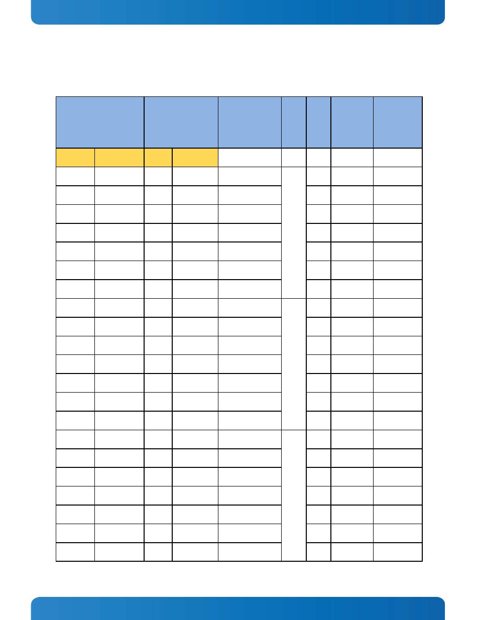
The following table details exactly how the NVIDIA Tegra parallel LCD pins are mapped to the on-Module Texas
Instruments SN75LVDS83B LVDS transmitter. For 18 bit displays, LVDS channels 0, 1, 2 are used. For 24 bit displays
(that accept 18 bit color packing), channels 0, 1, 2 and 3 are used.
NVIDIA T30 CPU
LVDS Transmitter (TI
SN75LVDS83B)
Net names
LV
D
S
C
h
a
n
n
el
Tr
a
n
smi
t
B
it
O
rd
er
18 Bit
standard
Color
mapping
24 Bit/18 bit
compatible
Color
mapping
Pin #
Pin Name
Pin #
Pin Name
AK12
LCD_D6
K5
D7
T30_LCD_D [6]
0
1
G0
G2
AH15
LCD_D17
J4
D6
T30_LCD_D [17]
2
R5
R7
AF13
LCD_D16
K3
D4
T30_LCD_D [16]
3
R4
R6
AE18
LCD_D15
J3
D3
T30_LCD_D [15]
4
R3
R5
AD12
LCD_D14
K2
D2
T30_LCD_D [14]
5
R2
R4
AC12
LCD_D13
K1
D1
T30_LCD_D [13]
6
R1
R3
AF9
LCD_D12
J2
D0
T30_LCD_D [12]
7
R0
R2
AF12
LCD_D1
D5
D18
T30_LCD_D [1]
1
1
B1
B3
AE8
LCD_D0
E5
D15
T30_LCD_D [0]
2
B0
B2
AJ12
LCD_D11
F6
D14
T30_LCD_D [11]
3
G5
G7
AK9
LCD_D10
G6
D13
T30_LCD_D [10]
4
G4
G6
AD15
LCD_D9
G5
D12
T30_LCD_D [9]
5
G3
G5
AG8
LCD_D8
J6
D9
T30_LCD_D [8]
6
G2
G4
AG16
LCD_D7
K6
D8
T30_LCD_D [7]
7
G1
G3
AG9
LCD_DE
A3
D26
T30_LCD_DE
2
1
DE
DE
AF10
LCD_VS
B4
D25
T30_LCD_VS
2
VS
VS
AF16
LCD_HS
A4
D24
T30_LCD_HS
3
HS
HS
AK10
LCD_D5
A6
D22
T30_LCD_D [5]
4
B5
B7
AK16
LCD_D4
B5
D21
T30_LCD_D [4]
5
B4
B6
AK15
LCD_D3
B6
D20
T30_LCD_D [3]
6
B3
B5
AD10
LCD_D2
C6
D19
T30_LCD_D [2]
7
B2
B4