Figure 7: fan connector (j1) location and pin-out, Table 15: fan connector (j1) pin-out, Figure 8: fan connector schematic – Kontron COMe-cOHXX User Manual
Page 55
Kontron COMe-cOH2/COMe-cOH6 User’s Guide
www.kontron.com
50
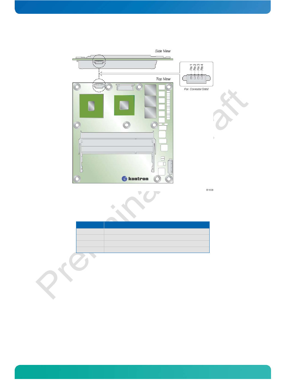
Figure 7: Fan Connector (J1) Location and Pin-Out
The onboard fan connector (J1) is on the left top side of the PCB. The
connection details are covered in the Figure 8 schematic.
Table 15: Fan Connector (J1) Pin-Out
Pin
Description
1
FAN_GND
2
FAN_12V_VCC
3
CPU_FAN_TACH_CONN
4
CPU_FAN_PWM_CONN
Figure 8: Fan Connector Schematic
To be supplied in a future version of this manual.
Connector J1 specifications and Kontron part numbers for the components are:
»
Part number: (Molex) 52435-2472
»
Mates with: (Molex) 51021-0400
»
Crimp terminals: (Molex) 50079-80000 (26-28 AWG)
See also other documents in the category Kontron Hardware:
- CP3003-SA uEFI BIOS (72 pages)
- CP3003-SA (36 pages)
- CP3002 (38 pages)
- CP3002-RC uEFI (64 pages)
- CP-RIO3-05 (42 pages)
- CP3002-RC (30 pages)
- CP342 (52 pages)
- CP930 (46 pages)
- CP932 (52 pages)
- CP346 (72 pages)
- CP384 (66 pages)
- CP383 (74 pages)
- CP382 (58 pages)
- CP381 (60 pages)
- CP372 (64 pages)
- CP371 (60 pages)
- CP-RIO3-04S (38 pages)
- CP390 (36 pages)
- CPS3410 (9 pages)
- CPS3402 (9 pages)
- CPS3105 (9 pages)
- CPS3101 (9 pages)
- CPS3003-SA (19 pages)
- PB-SIO4 (34 pages)
- PB-SIO4A (34 pages)
- PB-DOUT8 (34 pages)
- VMOD-2 (82 pages)
- VSBC-32 (110 pages)
- VM42 (62 pages)
- Bootstrap Loader (24 pages)
- VMP1 with Netbootloader (120 pages)
- VMP1 (106 pages)
- NetBootLoader (86 pages)
- VMP2 (142 pages)
- VMP3 (154 pages)
- CP-RIO6-923 (32 pages)
- CP-RIO6-923-F (32 pages)
- CP-RIO6-001 (28 pages)
- CP-RIO6-001-HD-VGA (46 pages)
- CP-RIO6-M (20 pages)
- CP-RIO6-B (28 pages)
- CP6925 (42 pages)
- CP6002 uEFI BIOS (76 pages)
- CP6002 IPMI (40 pages)
- CP6002 (42 pages)