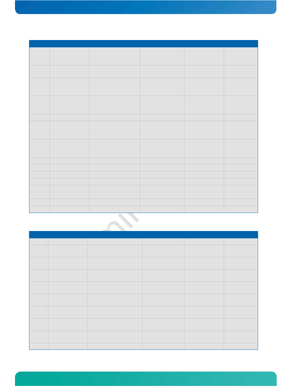
Table 4: connector x1a - row b – Kontron COMe-cOHXX User Manual
Page 26
Kontron COMe-cOH2/COMe-cOH6 User’s Guide
www.kontron.com
21
Pin
Signal
Description
Type
Termination Comment
A96
TPM_PP
Trusted Platform
Module Physical
Presence pin
I-3.3
A97
TYPE10#
Not connected for
Type 6 module
Not connected
nc
nc
A98
SER0_TX
Gen. Purpose
Serial Port 0
Transmit
Not connected
nc
nc
A99
SER0_RX
Gen. Purpose
Serial Port 0
Receive
Not connected
nc
nc
A100
GND (Fixed)
Power Ground
PWR
-
-
A101
SER1_TX
General Purpose
Serial Port 1
Transmit
Not connected
nc
nc
A102
SER1_RX
General Purpose
Serial Port 1
Receive
Not connected
nc
nc
A103
LID#
LID Button
I/OP-3.3
A104
VCC_12V
12V VCC
PWR
-
-
A105
VCC_12V
12V VCC
PWR
-
-
A106
VCC_12V
12V VCC
PWR
-
-
A107
VCC_12V
12V VCC
PWR
-
-
A108
VCC_12V
12V VCC
PWR
-
-
A109
VCC_12V
12V VCC
PWR
-
-
A110
GND
Power Ground
PWR
-
-
Table 4: Connector X1A - Row B
Pin
Signal
Description
Type
Termination Comment
B1
GND (Fixed)
Power Ground
PWR
-
-
B2
GBE0_ACT#
Ethernet Activity
LED
OD
FET PD
nc
B3
LPC_FRAME#
LPC Frame
Indicator
O-3.3
B4
LPC_AD0
LPC Address/Data
Bus
IO-3.3
B5
LPC_AD1
LPC Address/Data
Bus
IO-3.3
B6
LPC_AD2
LPC Address/Data
Bus
IO-3.3
B7
LPC_AD3
LPC Address/Data
Bus
IO-3.3
B8
LPC_DRQ0#
LPC Serial DMA
Request
I-3.3
B9
LPC_DRQ1#
LPC Serial DMA
Request
I-3.3
B10
LPC_CLK
LPC Clock
O-3.3