7 installation, 1 safety, 2 general instructions on usage – Kontron COMe-bP5020 User Manual
Page 69: Installation, Safety, General instructions on usage, 7 ins t allation
www.kontron.com
69
User Guide
COMe-bP5020
7 Ins t allation
7.1 Safety
This Kontron product was developed and tested carefully to provide all features necessary to ensure its compliance with elec-
trical safety requirements. It was also designed for a long fault-free life. However, the life expectancy of this product can be
drastically reduced by improper treatment during unpacking and installation. Therefore, in the interest of personnel safety
and of the correct operation of this product, it is recommended to conform with the following guidelines.
» Electronic boards and their components are sensitive to static electricity. Therefore, care must be taken during all han-
dling operations and inspection of this product in order to ensure product integrity at all times.
» Do not handle this product out of its protective enclosure while it is not used for operational purposes unless it is oth-
erwise protected.
» Whenever possible, unpack or pack this product only at EOS/ESD safe work stations. Where a safe work station is not guar-
anteed, it is important for the user to be electrically discharged before touching the product with his/her hands or tools.
This is most easily done by touching a metal part of the system housing before touching the product.
7.2 General Instructions on Usage
In order to maintain Kontron’s product warranty, this product must not be altered or modified in any way. Changes or modifi-
cations to the device, which are not explicitly approved by Kontron and described in this manual or received from Kontron’s
Technical Support as a special handling instruction, will void your warranty.
This device should only be installed in or connected to systems that fulfill all necessary technical and specific environmental re-
quirements. This applies also to the operational temperature range of the specific board version, which must not be exceeded.
7.3 COM Express® Module-to-Carrier Assembly Considerations
The COMe-bP5020 has been designed to the COM Express® specification for form factor, mechanical dimensions and mounting
hole layout. Provisions have also been made for assembly of a heat spreader (two dedicated mounting holes). Kontron offers
three cooling solutions (as indicated in Chapter 5) all of which cover the entire upper area of the board. All of the solutions
have appropriate holes for mounting hardware (screws, standoffs, etc.).
As each cooling solution is a function of the application, it is the responsibility of the implementer to ensure proper assembly
of the COMe-bP5020 with the carrier board and where appropriate attachment of the combined assembly to a chassis wall, a
heatpipe or other such devices.
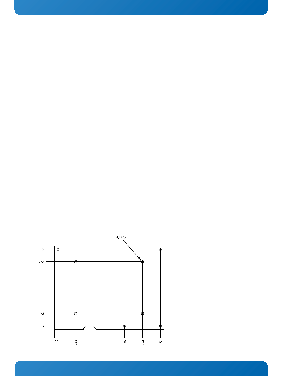
The heat spreader of the COMe-bP5020 has four threaded mounting holes for attaching cooling solutions as indicated in the
figure below. Screws used for mounting must not extend beyond the bottom side of the heat spreader when installed, otherwise
damage to the COMe-bP5020 will result. The torque applied to these screws when assembling must not exceed 0.7 Nm.
Figure 9: COMe-bP5020 Heatspreader Cooling Solution Mounting Hole Layout