General signal description – Kontron COMe-bP5020 User Manual
Page 26
www.kontron.com
26
User Guide
COMe-bP5020
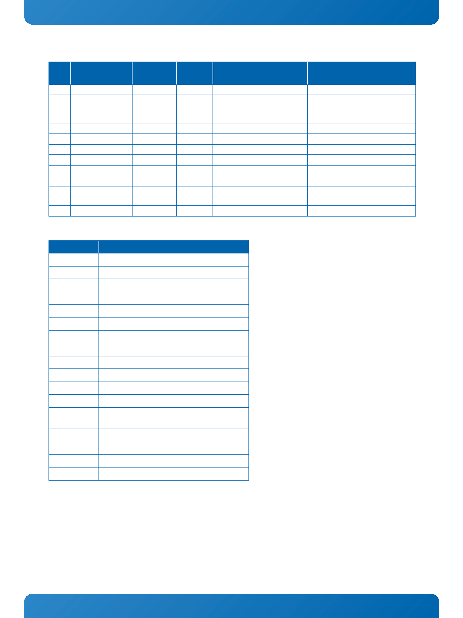
Table 8: General Signal Description
D96
GND
PWR
PWR
D97
LA19 / GPIO11
Local Bus /
GPIO
I/O-3.3
weak PU when conf igured for
GPIO
multiplexed CPU address/data sig-
nal or GPIO depending on SCONF
setting
D98
N/C
SERDES
D99
N/C
SERDES
D100 GND
PWR
PWR
D101 N/C
N/C
D102 N/C
N/C
D103 GND
PWR
PWR
D104..
D109
VCC_12V
PWR
PWR
nominal 12V
D110
GND
PWR
PWR
TYPE
DESCRIPTION
I/O-3.3
Bi-directional 3.3V IO signal
I-3.3
3.3V input
O-3.3
3.3V output
OD-3.3
Open-Drain output
I-2.5
2.5V input
O-2.5
2.5V output
I/O-1.2
Bi-directional 1.2V IO signal
O-1.2
1.2V output
DP-I/O
Differential pair input/output
DP-I
Differential pair input
DP-O
Differential pair output
PDS
PullDown Strap / COM Express® type coding
STRAP
Straping input during power-up (do not connect
any external Pullup or Pulldown resistor)
PWR
Power connection
PWR 3V
RTC data retention 3.3V power
PWR 5V
Standby power
N/C
Not connected
Table 7: Connector J2 Row D Pinout (cont’d)
PIN
SIGNAL
SIGNAL
GROUP
TYPE
TERMINATION
COMMENT
- CP3003-SA uEFI BIOS (72 pages)
- CP3003-SA (36 pages)
- CP3002 (38 pages)
- CP3002-RC uEFI (64 pages)
- CP-RIO3-05 (42 pages)
- CP3002-RC (30 pages)
- CP342 (52 pages)
- CP930 (46 pages)
- CP932 (52 pages)
- CP346 (72 pages)
- CP384 (66 pages)
- CP383 (74 pages)
- CP382 (58 pages)
- CP381 (60 pages)
- CP372 (64 pages)
- CP371 (60 pages)
- CP-RIO3-04S (38 pages)
- CP390 (36 pages)
- CPS3410 (9 pages)
- CPS3402 (9 pages)
- CPS3105 (9 pages)
- CPS3101 (9 pages)
- CPS3003-SA (19 pages)
- PB-SIO4 (34 pages)
- PB-SIO4A (34 pages)
- PB-DOUT8 (34 pages)
- VMOD-2 (82 pages)
- VSBC-32 (110 pages)
- VM42 (62 pages)
- Bootstrap Loader (24 pages)
- VMP1 with Netbootloader (120 pages)
- VMP1 (106 pages)
- NetBootLoader (86 pages)
- VMP2 (142 pages)
- VMP3 (154 pages)
- CP-RIO6-923 (32 pages)
- CP-RIO6-923-F (32 pages)
- CP-RIO6-001 (28 pages)
- CP-RIO6-001-HD-VGA (46 pages)
- CP-RIO6-M (20 pages)
- CP-RIO6-B (28 pages)
- CP6925 (42 pages)
- CP6002 uEFI BIOS (76 pages)
- CP6002 IPMI (40 pages)
- CP6002 (42 pages)