Connector j2 row d pinout – Kontron COMe-bP5020 User Manual
Page 24
www.kontron.com
24
User Guide
COMe-bP5020
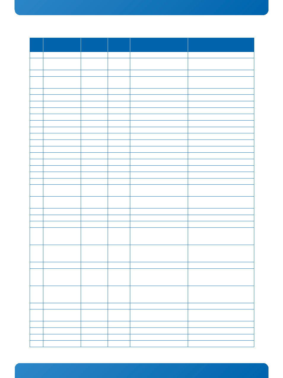
Table 7: Connector J2 Row D Pinout
PIN
SIGNAL
SIGNAL
GROUP
TYPE
TERMINATION
COMMENT
D1
GND
PWR
PWR
D2..
D10
N/C
N/C
D11
GND
PWR
PWR
D12..
D16
N/C
N/C
D17
LCS0#
Local Bus
O-3.3
connected to CPU LCS1#
D18
LCS1#
Local Bus
O-3.3
connected to CPU LCS7#
D19
SERDES_TX6+
SERDES
DP-O
AC coupled on module (100n)
SerDes Bank 1G
D20
SERDES_TX6-
SERDES
DP-O
AC coupled on module (100n)
SerDes Bank 1G
D21
GND
PWR
PWR
D22
SERDES_TX7+
SERDES
DP-O
AC coupled on module (100n)
SerDes Bank 1H
D23
SERDES_TX7-
SERDES
DP-O
AC coupled on module (100n)
SerDes Bank 1H
D24
LA31
Local Bus
O-3.3
D25
LA30
Local Bus
O-3.3
D26
N/C
N/C
D27
N/C
N/C
D28
GND
PWR
D29
N/C
N/C
D30
N/C
N/C
D31
GND
PWR
PWR
D32..
D34
N/C
N/C
D35
LALE
Local Bus
STRAP/
O-3.3
PU 4k7
Local Bus address latch enable
D36
N/C
N/C
D37
N/C
N/C
D38
GND
PWR
D39
SER0_CTS#
UART
I-3.3
PU 10k
UART[1]_CTS on CPU when conf ig-
ured for 2UART-Mode / UART[3]_RX
in 4 UART-Mode
D40
SER0_RTS#
UART
O-3.3
UART[1]_RTS on CPU when config-
ured for 2UART-Mode / UART[3]_TX
in 4 UART-Mode
D41
GND
PWR
PWR
D42
SER1_CTS#
UART
I-3.3
PU 10k
UART[2]_CTS on CPU when conf ig-
ured for 2UART-Mode / UART[4]_RX
in 4 UART-Mode
D43
SER1_RTS#
UART
O-3.3
UART[2]_RTS on CPU when config-
ured for 2UART-Mode / UART[4]_TX
in 4 UART-Mode
D44
LBCTL
Local Bus
O-3.3
Local Bus buffer control
D45
LGTA#
Local Bus
O-3.3
Local Bus external access termina-
tion signal
D46
IRQ3#
IRQ
I-3.3
PU 4k7
can be routed to CPU-IRQ[7..11]#
D47
IRQ4#
IRQ
I-3.3
PU 4k7
can be routed to CPU-IRQ[7..11]#
D48
LA29
Local Bus
O-3.3
D49
LA28
Local Bus
O-3.3