10 spi, 11 serial interface, 12 smb / i2c – Kontron COMe-bP5020 User Manual
Page 30: Serial interface, Smb / i2c, Spi signal configurations, I2c device resources
www.kontron.com
30
User Guide
COMe-bP5020
2.5.2.10 SPI
The Serial Peripheral Interface Bus or SPI bus is a synchronous serial data link standard developed by Motorola that operates
in full duplex mode. Devices communicate in master/slave mode where the master device initiates the data frame. Multiple
slave devices are allowed with individual slave select (chip select) lines. Sometimes SPI is called a “four wire” serial bus, con-
trasting with three, two, and one wire serial buses.
For a detailed signal description please refer to the COM Express® base specification, chapter 4.3.12.
The COMe-bP5020 supports boot from an external SPI flash. Therefore it can be configured via pin B88 (BIOS_DIS1#) for the
following configurations:
Table 10: SPI Signal Conf igurations
The BIOS_DIS0# signal defined in the COM Express® Base specification is not used by the COMe-bP5020.
2.5.2.11 Serial Interface
Up to four UART interfaces are available on the COMe-bP5020. The following configurations are possible:
» 2x 4-wire UARTs (factory configuration)
» 4x 2-wire UARTs
The configuration of the UART modes can be done using the U-Boot “sconf” command.
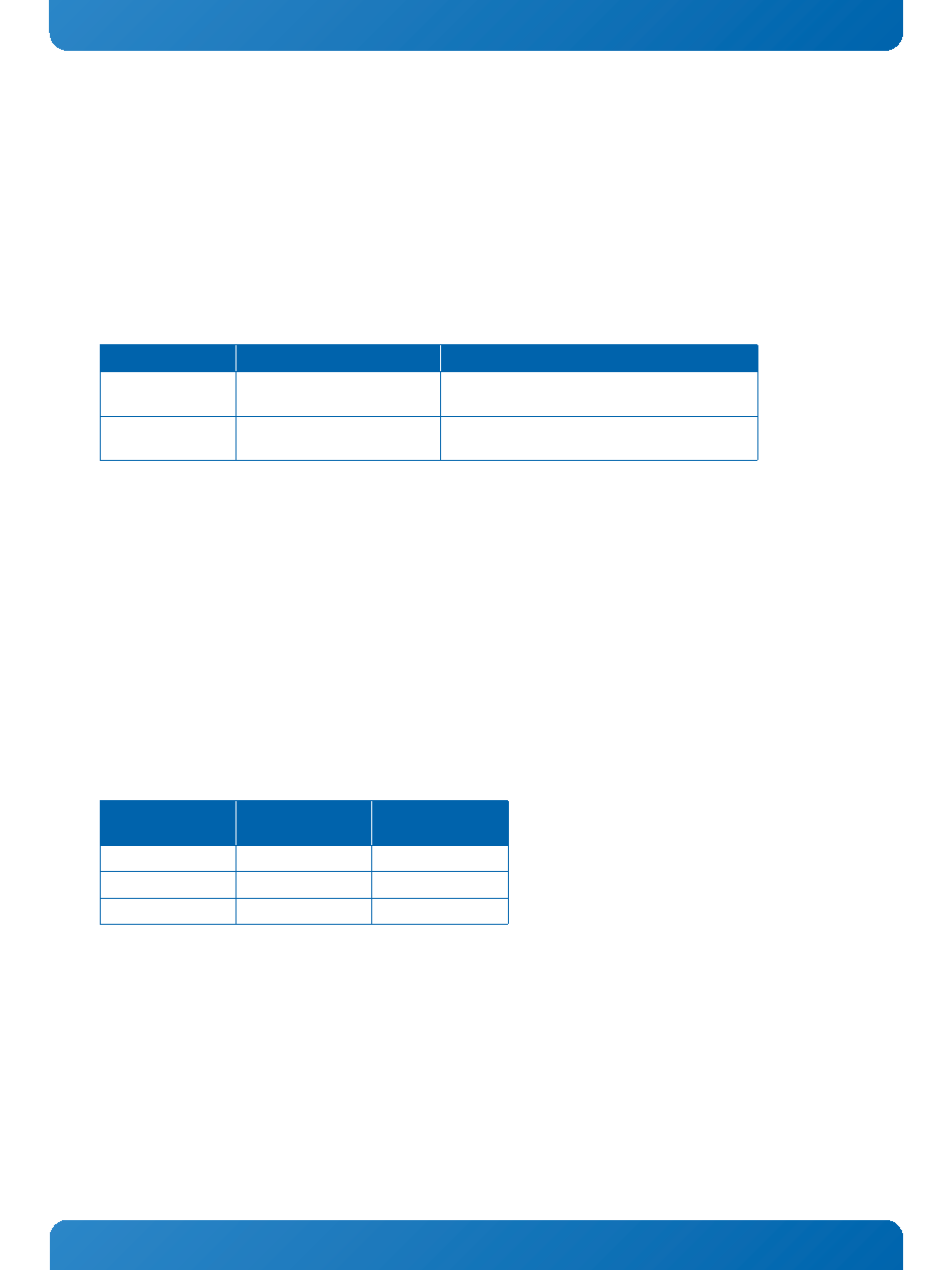
2.5.2.12 SMB / I2C
The COMe-bP5020 provides two I2C controllers with speeds up to 400 kHz for application usage. The signals on the COM
Express® connector labeled SMB_CK and SMB_DAT are connected to the I2C controller IIC2 of the P5020. The resources
occupied by the devices are as follows:
Table 11: I2C Device Resources
The signals on the COM Express® connector labeled I2C_CK and I2C_DAT are connected to the I2C controller IIC4 of the P5020.
This controller is reserved for application use only on the COMe-bP5020.
BIOS_DIS1#
FUNCTION
SIGNAL ROUTING
Open
Boot from on-module flashes
P5020 eSPI chip select SPI_CS2# is available on
the carrier
Pulled to GND
Boot from external flash
P5020 eSPI chip select SPI_CS0# (boot chip
select) is available on the carrier
DEVICE
I2C ADDRESS
(binary)
I2C ADDRESS
(hex)
User EEPROM
1010 110x
0xAC
RTC
1010 001x
0xA2
Thermal Sensor
1001 001x
0x92