2 gpio, 8 usb, 9 sdhc (sdio) – Kontron COMe-bP5020 User Manual
Page 29: Gpio, Sdhc (sdio), Examples of local bus and gpio configurations
www.kontron.com
29
User Guide
COMe-bP5020
2.5.2.7.2 GPIO
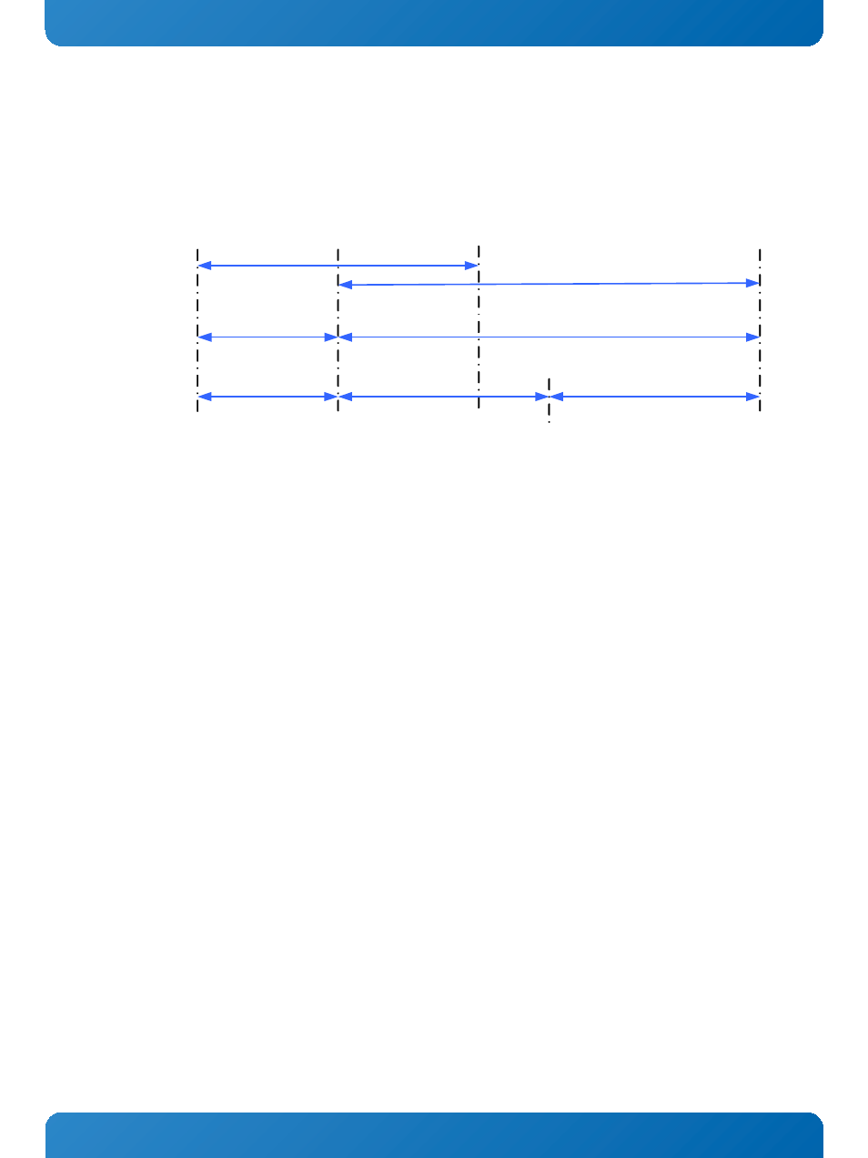
The COMe-bP5020 provides the possibility to convert some of the Local Bus signals to GPIO functionality. There are 12 signals
on the COM Express® connector which can be multiplexed between Local Bus functionality and GPIO functionality in groups of
4 signals.
F igure 4: Examples of Local Bus and GPIO Conf igurations
The selection which function the dedicated group should have can be done with the “sconf” command in U-Boot depending on
the required Local Bus data path width and Local Bus address range.
2.5.2.8 USB
There are five USB 2.0 high speed USB ports available on the COMe-bP5020.
The USB ports USB0..3 at the COM Express® connectors are provided using a 4-port USB hub with its Uplink-Port connected to
the USB controller USB1 on the QorIQ™ P5020.
USB port USB4 at the COM Express® connector is connected directly to the USB2 controller of the QorIQ™ P5020. This port is
capable of providing USB host or USB device functionality.
The configuration for host or device functionality is done using the U-Boot “sconf” command.
2.5.2.9 SDHC (SDIO)
The Freescale™ QorIQ™ CPUs incorporate an enhanced Secure Digital Host Controller (eSDHC) which provides support for
MultiMediaCards (MMC) and Secure Digital (SD) Cards.
The interfacing signals of the CPU are multiplexed between the onboard SD card socket and the dedicated SDIO signals on the
COM Express® connectors. The selection between the onboard socket and external interfacing is done via the DIP Switch SW1,
switch 3.
16-bit data path
8MB addressable
Configuration
examples
16-bit Databus
8MB Address Range
8-bit Databus
12x GPIO
0
15
31
0
0
7
8
31
8
19
8-bit data path
8MB addressable
8MB Address Range
8-bit Databus
20
31
8
4kB Address Range
8-bit data path
4kB addressable +
12 GPIOs