3 gbe ports, Gbe ports - 28, At8402 hardware description – Kontron AT8402 User Manual User Manual
Page 61
AT8402
Hardware Description
Page 3 - 28
AT8402 User Guide
3.2.3
GbE Ports
The GE1 and GE2 ports are connected to the front board's GbE switch. The GbE PHY device
is placed on the front board, the magnetics are integrated into the x4 RJ45 connector. The con-
nectors’ pinning is set to MDI-X mode.
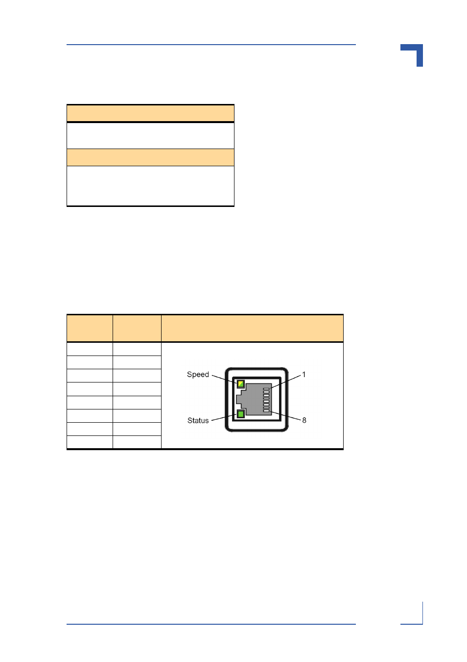
Table 3-24: Fast Ethernet Management (RJ45) LEDs Signification
Speed LED (Yellow)
OFF
10BASE-T
ON
100BASE-TX
Status LED (Green)
OFF
Link down
ON
Link up and no activity
BLINK
Link up and activity
Table 3-25: GbE Pin Assignment
Pin
Number
Signal
1
BI_DB+
2
BI_DB-
3
BI_DA+
4
BI_DD+
5
BI_DD-
6
BI_DA-
7
BI_DC+
8
BI_DC-
See also other documents in the category Kontron Hardware:
- CP3003-SA uEFI BIOS (72 pages)
- CP3003-SA (36 pages)
- CP3002 (38 pages)
- CP3002-RC uEFI (64 pages)
- CP-RIO3-05 (42 pages)
- CP3002-RC (30 pages)
- CP342 (52 pages)
- CP930 (46 pages)
- CP932 (52 pages)
- CP346 (72 pages)
- CP384 (66 pages)
- CP383 (74 pages)
- CP382 (58 pages)
- CP381 (60 pages)
- CP372 (64 pages)
- CP371 (60 pages)
- CP-RIO3-04S (38 pages)
- CP390 (36 pages)
- CPS3410 (9 pages)
- CPS3402 (9 pages)
- CPS3105 (9 pages)
- CPS3101 (9 pages)
- CPS3003-SA (19 pages)
- PB-SIO4 (34 pages)
- PB-SIO4A (34 pages)
- PB-DOUT8 (34 pages)
- VMOD-2 (82 pages)
- VSBC-32 (110 pages)
- VM42 (62 pages)
- Bootstrap Loader (24 pages)
- VMP1 with Netbootloader (120 pages)
- VMP1 (106 pages)
- NetBootLoader (86 pages)
- VMP2 (142 pages)
- VMP3 (154 pages)
- CP-RIO6-923 (32 pages)
- CP-RIO6-923-F (32 pages)
- CP-RIO6-001 (28 pages)
- CP-RIO6-001-HD-VGA (46 pages)
- CP-RIO6-M (20 pages)
- CP-RIO6-B (28 pages)
- CP6925 (42 pages)
- CP6002 uEFI BIOS (76 pages)
- CP6002 IPMI (40 pages)
- CP6002 (42 pages)