Hardware description, 1 base board, Hardware description - 2 – Kontron AT8402 User Manual User Manual
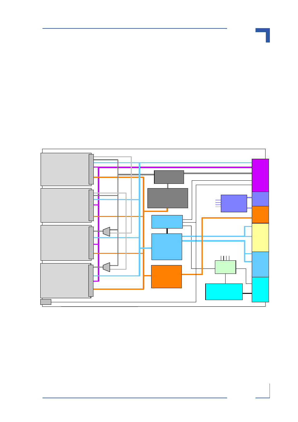
Page 35: 1 base board - 2, Functional block diagram base board - 2, At8402 hardware description, Base if zone 2 fabric if zo ne 2 z one 1, Rtm i f zone 3
AT8402
Hardware Description
Page 3 - 2
AT8402 User Guide
B
ase IF
Zone 2
Fabric
IF
Zo
ne
2
Z
one
1
Telc
o
Cl
k
8
Switch Controller
Gigabit
Ethernet
Switch
RTM I
F
Zone 3
SAS
Expander
4
8
4
4
AMC B2
AMC Conn
ec
to
r
AMC B3
AM
C Co
n
n
e
c
to
r
AMC B4
4
2
PCI
4
4
SAS
Controller
To all
AMC
slots
Telco/PCIe
Clk
PCI
Express
Switch
4x8
4
4
4
RS232
FE
AMC Con
n
ec
to
r
AMC B1
A
M
C Co
n
n
e
c
to
r
Power
Mezzanine
Up
dat
e
IF
IPMI
To all AMC slots
2
2
2
2
RS232
3.
Hardware Description
This chapter describes the board specific items of the AdvancedTCA AMC Carrier Board
AT8402 consisting of the main assembly with the Power Mezzanine Module. Also described is
the RTM8400 used for management access and I/O extension.
3.1
Base Board
The base board is a PICMG 3.0 and 3.1 Option 3 compliant Carrier Board for AdvancedTCA
shelves offering up to four mid-size AMC bays.
Figure 3-1: Functional Block Diagram Base Board