3 system airflow, System airflow, Figure 6-1: pressure drop curve – Kontron AT8940 User Manual
Page 74: Table 6-2 pressure curve at8940
Thermal Considerations
59
www.kontron.com
6.1.3
System Airflow
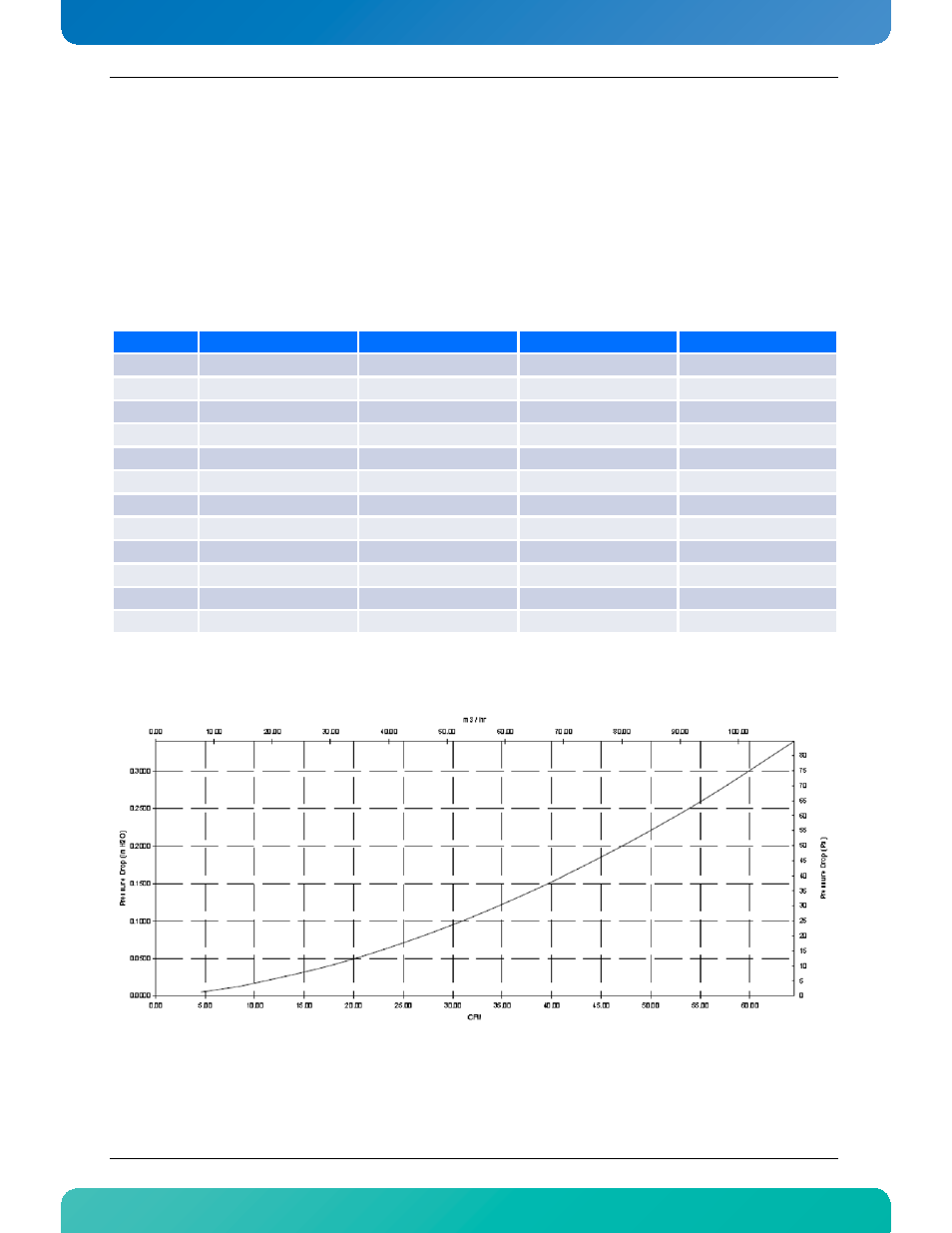
The airflow impedance (pressure) curve gives multiple information and tips about thermal operational range
of the system carrying the AT8940. Once volumetric airflow capability of your chassis is known, the pressure
curve can help determine the ambient (room) temperature setpoint that should be used for optimal
operation. If you are using various models of ATCA blades into the same chassis, it is possible to find the best
thermal fit. Having the volumetric airflow value for each chassis slot, it is then possible to decide the layout
using the pressure curves.
Table 6-2:Pressure curve AT8940
Figure 6-1:Pressure Drop Curve
Test Poin
Airflow (CFM)
Pressure drop (in H2O)
Airflow (m³/h)
Pressure Drop (Pa)
1
5
0.005
8.5
1.3
2
10
0.017
17.0
4.3
3
15
0.032
25.5
8.1
4
20
0.050
34.0
12.6
5
25
0.071
42.5
17.8
6
30
0.095
51.0
23.7
7
35
0.122
59.5
30.5
8
40
0.152
68.0
37.9
9
45
0.185
76.5
46.1
10
50
0.221
85.0
55.0
11
55
0.260
93.4
64.6
12
60
0.302
101.9
75.0