Board features, 1 block diagram, Figure 2-1: block diagram – Kontron AT8940 User Manual
Page 25
Board Features
10
www.kontron.com
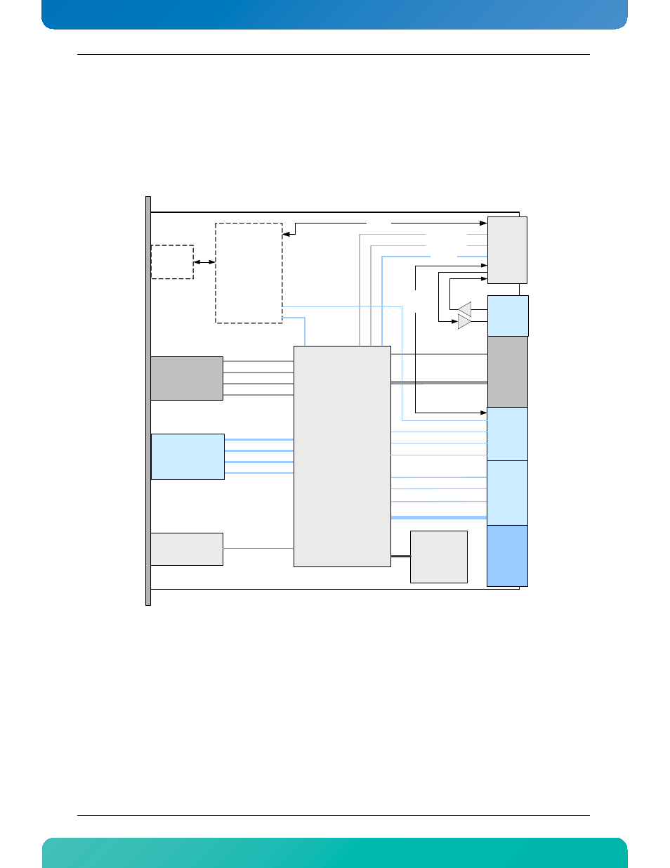
2. Board Features
2.1
Block Diagram
Figure 2-1:Block Diagram
The Ethernet Switch Block consists of the Fabric Interface Switch, the Base Interface Switch and the Unit
Computer managing both.
To 14 Slots: 10/40G
Inter Hub: 10/40G
Base
Uplinks
Z
one 1
to ShMC A (FE)
14 Node Slots
to ShMC B (FE)
Inter Hub
1x GE Mgmt. and
2x Serial Console
Fabri
c
IF
Zon
e
2
Upd
a
te
IF
B
ase I
F
Z
one 2
Fabric
Uplinks
Power
IPMI
TE
L
C
O
Cl
oc
k
4x 1/10GbE
SFP+ Cages
4x 1/10GbE
SFP+ Cages
Telco
Clock
sync
XLAUI / 4x XFI
3x SGMII
2nd Inter Hub (option)
XLAUI / 4x XFI
System
Manager
COM
Express
+
Storage
(optional)
2x SATA
GE Mgmt
USB
Console
1GbE
1GbE
1GbE to other BI
X
Ethernet
Switch Block
RT
M IF
Z
one 3
from other System Mgr
To other Unit Computer
Management
This manual is related to the following products: