3 eb8541 e·brain™ module interfaces, 1 system interface, 2 system interface extension – Kontron VMP3 User Manual
Page 40: 3 communications interface, 3 eb8541 e²brain™ module interfaces - 6, System interface - 6, System interface extension - 6, Communications interface - 6, System interface signal types - 6, System interface extension signal types - 6
Functional Description
VMP3
Page 2 - 6
© 2005 Kontron Modular Computers GmbH
ID 29230, Rev. 01
29230
.01.UG.VC.050727/091420
P R E L I M I N A R Y
2.3
EB8541 E²Brain™ Module Interfaces
The following sections provide a very brief description of the interfacing between the E²Brain™
module and the EBC-VME3 board.
2.3.1
System Interface
As the name implies, this interface provides the basic application connection functionality re-
quired to integrate the EB8541 E²Brain™ module as the high performance core of the VMP3.
The System Interface is realized using a 140-pin, HIROSE FX8C-140P-SV connector. The fol-
lowing table provides an overview of the signal types and a brief description of the interfacing
realized on this connector.
2.3.2
System Interface Extension
The System Interface Extension is realized using an 80-pin, HIROSE FX8C-80P-SV connector,
and it is used to provide CPU architecture specific system interfaces.
In the case of the VMP3, a CompactFlash interface is made available on the System Interface
Extension.
2.3.3
Communications Interface
The Communications Interface Connector is used to provide a set of standard communications
interfaces. In the case of the VMP3, there are three types of interfaces provided: four high
speed serial interfaces, one CAN interface, and one Fast Ethernet interface.
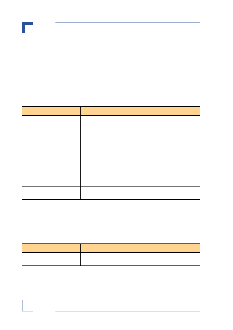
Table 2-1: System Interface Signal Types
SIGNAL TYPE
DESCRIPTION
POWER
VMP3 E²Brain™ module input power, grounds, battery backup power, PCI
signaling voltage V(I/O)
MONITOR AND CONTROL (M/C)
Control signals for E²Brain™ module operation, configuration, and addi-
tional GPIO interfacing
TEST AND PROGRAMMING (T/P)
JTAG/Debug signals for Emulator interfacing
TERMINAL AND
CONSOLE (T/C)
Two 2-wire serial interfaces:
RxD1/TxD1: Used by the boot loader during startup as a terminal interface;
once the system has been booted, is available as general pur-
pose serial interface (Terminal)
RxD2/TxD2: general purpose serial interface (Console)
I2C
One I2C standard interface for low speed, serial, inter-chip communica-
tions
LPC
One LPC standard interface for (GP)IOs and simple memory interfacing
PCI
One PCI standard interface for PCI-bus interfacing
Table 2-2: System Interface Extension Signal Types
SIGNAL TYPE
DESCRIPTION
COMPACTFLASH
One CompactFlash interface (true IDE mode)
POWER
VMP3 E²Brain™ module input power and grounds