3 vmebus control/status register, Vmebus control/status register - 7, Vsbc-32 configuration – Kontron VSBC-32 User Manual
Page 67
VSBC-32
Configuration
ID 21168, Rev. 04
Page 4 - 7
©
PEP Modular Computers GmbH
4.2.3
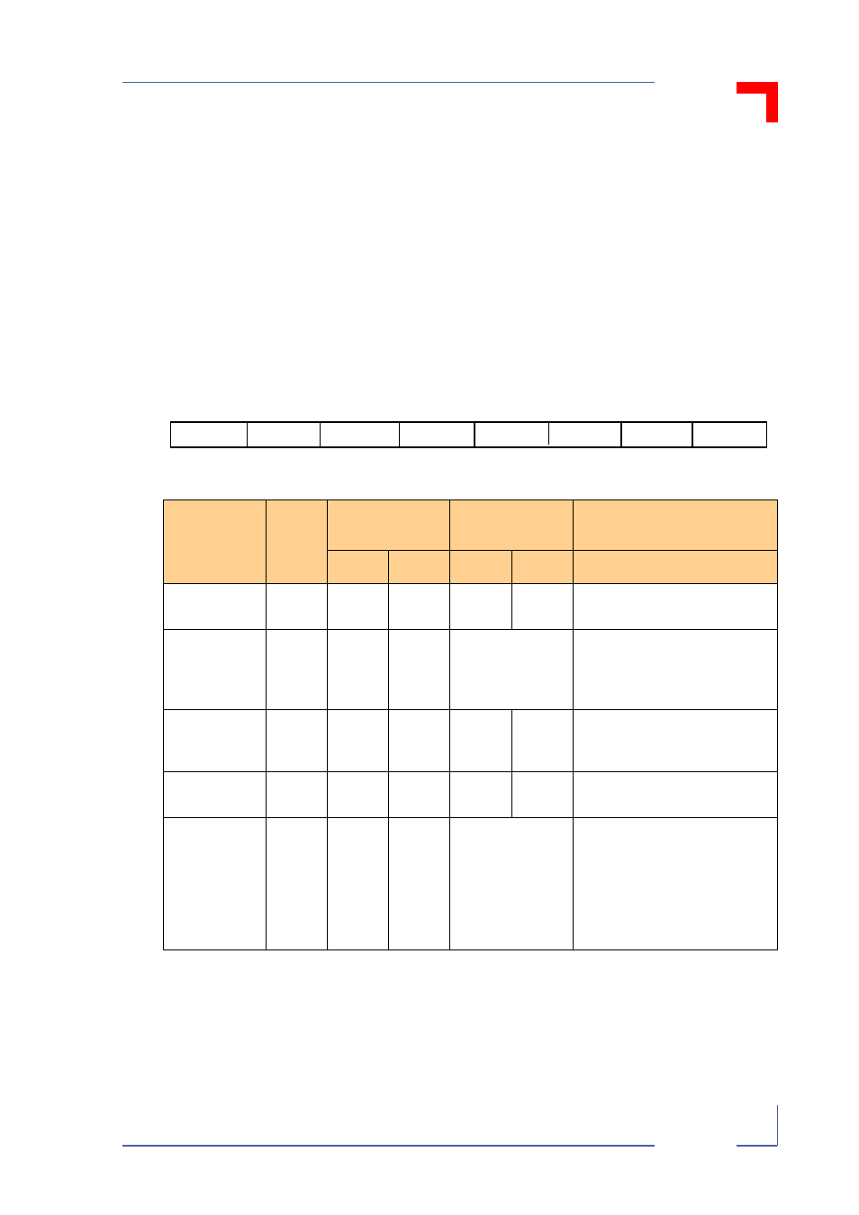
VMEbus Control/Status Register
Figure 4-3:
CS7 + 0x5 Bitmap
Address:
CS7 + 0x5
Format:
Byte
Access:
Read/write
Value after HW Reset:
See table
PEP Default Address:
0x 0D 00 00 05
Table 4-7: Register Description
Name
Register
Value
HW Reset Value
SW Reset Value
(PEP)
Description
Slot 1
Other
Slot 1
Other
P_IRQ5
bit 7
1
0
0
0
0
Mailbox interrupt pending.
EN_DPR
bit 6
1
0
0
Value stored in
EEPROM
Dual-port SRAM (incl. mailbox
interrupts) enabled for VMEbus
requester. Base address estab-
lished through bits BADR0..3.
EN_BERR2
bit 5
1
0
0
1
0
Enables the VMEbus error timer
(all VMEbus cycles).
Timeout = 128µ s.
FSD
bit 4
1
1
0
1
0
VMEbus “slot 1” detection flag of
system controller..
BADR3..0
bits 3..0
0
0
Value stored in
EEPROM
VMEbus address location of dual-
ported SRAM. Equivalent to
VMEbus address lines A23..A20,
programmable from 0x 00..0x 0F
in 1MB windows. Enabled by
EN_DPR
:.
(See also following table.)
BADR2
BADR3
BADR1
BADR0
0
1
2
3
4
5
6
7
P_IRQ5
FSD
EN_BERR2
EN_DPR