9 address decoder, 1 basic structure, 2 boot decoding – Kontron VSBC-32 User Manual
Page 55: Address decoder - 23, Basic structure - 23, Boot decoding - 23, Vsbc-32 functional description
VSBC-32
Functional Description
ID 21168, Rev. 04
Page 2 - 23
©
PEP Modular Computers GmbH
2.9 Address Decoder
2.9.1
Basic Structure
The address decoder of the VSBC-32(E) consists of external logic and the
MC68(EN)360 internal memory controller. The MC68(EN)360’s internal chip select logic
decodes all the basic address areas following its initialization. The eight chip select out-
puts of the processor are connected to the different devices as shown in the following
tablle.
1
Chip selects for flash on memory piggybacks and EPROM sockets are exchanged depending on the selected boot
device (Jumper J18).
The external address decoder switches the boot chip select CS0, memory piggyback or
EPROM on flash/EPROM sockets depending on the selected boot device. The interrupt
acknowledge cycles are also decoded by the external address decoder. Moreover, the
external address decoder includes a fast bus error (BERR) generator which monitors
the delay between external cycle start and generated CSx line.
2.9.2
Boot Decoding
The type of boot device can be selected from the DRAM/flash memory piggyback or the
EPROM devices on the two flash/EPROM sockets. The flash/EPROM sockets can be
configured by the user with the EPROM or different flash devices. Please note that
regardless of the boot device selected both possible areas can be addressed due to the
fact that each area is connected to a seperate CS line of the controller. This means that
the CS0 line, which is the global boot select of the controller, is exchanged for the CS3
line by the boot decoder logic.
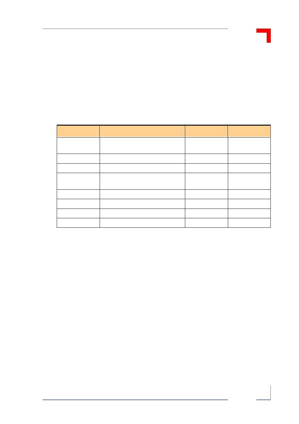
Table 2-8: Chip Select Output Connection
Chip Select
Connection
Port Size
Acknowledge
CS0
Flash on memory piggyback or EPROM
on flash/EPROM sockets
1
32/16
Internal
CS1
DRAM on memory piggyback
32
Internal
CS2
VMEbus
16
External
CS3
Flash/EPROM sockets or
memory piggyback
1
16/32
Internal
CS4
SRAM
16
External
CS5
CXC
16
External
CS6
RTC
16
External
CS7
Control/status register
16
External