4 board interfaces, 1 serial i/o interfaces, Board interfaces - 11 – Kontron VSBC-32 User Manual
Page 43: Serial i/o interfaces - 11, Vsbc-32 functional description
VSBC-32
Functional Description
ID 21168, Rev. 04
Page 2 - 11
©
PEP Modular Computers GmbH
2.4 Board Interfaces
The following section provides a description of the mainboard interface connector
pinouts. For a detailled list and description of the connectors of the serial interface/com-
munication piggybacks and of the frontpanel interface connectors please refer to the “SI
Piggybacks” appendix of this manual as well as to the CXM-SIO3 user’s manual and its
“Serial Communications Piggybacks” appendix respectively.
2.4.1
Serial I/O Interfaces
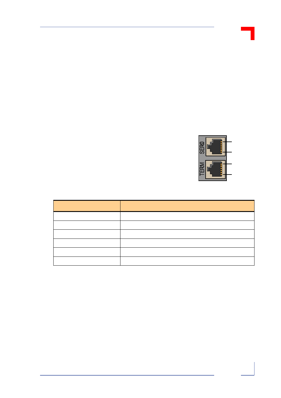
The mainboard RJ12 RS232 frontpanel connec-
tors BU7 and BU8 of the VSBC-32(E) are pro-
vided with TxD and RxD signals by the controller’s
SMC1 and SMC2 channels and supply RS232
interface software handshake (XON/XOFF) capa-
bility. They are configured as service/debug con-
nectors by default.
The pinouts of the RJ12 connectors are shown in
the following table.
N/C = Not connected.
Table 2-3: Pinouts of the Mainboard Serial Interface Connectors BU7/BU8
Pin
Pinouts
1
N/C
2
GND
3
TxD
4
RxD
5
N/C
6
N/C
6
1
SMC1
6
1
SMC2
Figure 2-5: Orientation of
the VSBC-32(E) Mainboard
Serial Interfaces