ETS-Lindgren 2181 Turntable User Manual
Page 24
24
| Assembly
and
Installation
•
Small flat blade screwdriver
•
Phillips #2 bit driver
• Adhesive
tape
I
NSTALLATION
S
TEPS
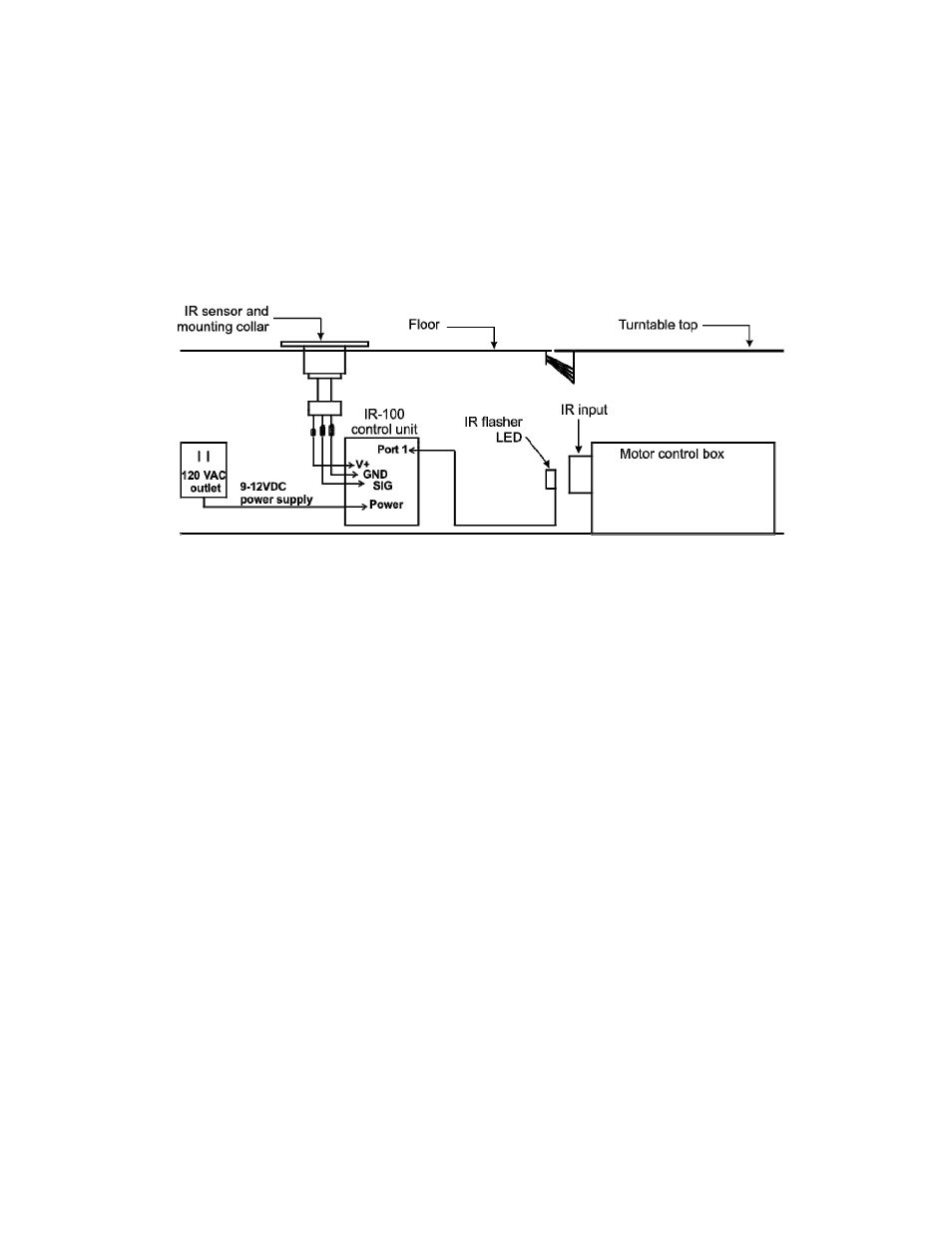
1. Choose a location for the IR infrared sensor that is away from traffic.
2. Using a 1-in hole saw, cut an opening in the floor for the IR sensor.
3. Connect the V+, GND, and SIG wires to the IR sensor as shown in the
diagram, and feed the cable through the hole.
4. Use the 1/16-in drill bit and four flathead mounting screws to mount the
IR sensor collar.
5. Connect the V+, GND, and SIG wires from the IR sensor to the
IR-100 control unit as shown in the diagram.
6. Using adhesive tape, attach the IR flasher LED directly over the IR input
on the motor control box.
7. Connect the IR flasher to port 1 on the IR-100 control unit.
8. Plug the 9-12VDC power supply into the power connector on the
IR-100 control unit, and then plug the power supply into a 120 VAC
outlet.
- SMART 200 Reverb Chambers (45 pages)
- 6402 Helmholtz Coil (24 pages)
- 3625-2 LISN (15 pages)
- 3701 Line Probe (15 pages)
- 3725-2M LISN (19 pages)
- 3810-2 LISN (25 pages)
- 3816-2 LISN (21 pages)
- 3850-2 LISN (19 pages)
- 4825-2 LISN (25 pages)
- 1052 Antenna Tower Positioner (23 pages)
- 2005 Single Axis Positioner (32 pages)
- 2090 Controller (178 pages)
- 2110 Multi-Axis Positioning Systems (MAPS) (48 pages)
- 2115 Multi-Axis Positioning Systems (MAPS) (48 pages)
- 2165 Turntable (46 pages)
- 2171B Boresight Antenna Tower (64 pages)
- 2175 Antenna Tower (41 pages)
- 2187 Turntable (36 pages)
- 2188 Turntable (39 pages)
- 7-TR Tripod Positioner (49 pages)
- 7000-001 EMCenter Modular RF Platform (41 pages)
- 7405 E & H Near Field Probe Set (51 pages)
- 91197-1 Current Probe (57 pages)
- 95236-1 Current Probe (27 pages)
- HI-1501 Microwave Oven Survey Meter (28 pages)
- HI-1600 Microwave Oven Survey Meter (26 pages)
- HI-1710A Microwave Oven Survey Meter (57 pages)
- HI-1801 Microwave Oven Survey Meter (24 pages)
- HI-2200 RF Survey Meter (53 pages)
- HI-2602 Interlock Monitor (22 pages)
- HI-2790B Calibration Comparison System (44 pages)
- HI-3603 VLF Survey Meter (55 pages)
- HI-3604 ELF Survey Meter (44 pages)
- HI-3624(A) Survey Meter (22 pages)
- HI-3627 ELF Magnetic Field Meter (36 pages)
- HI-3637 VLF Magnetic Field Meter (48 pages)
- HI-3638 ELV/VLF Electric Field Meter (41 pages)
- HI-3702 Induced Current Meter (34 pages)
- HI-3804 RF Industrial Compliance Meter (25 pages)
- HI-4416 Numeric EMF Readout Unit (38 pages)
- HI-4433-CH Magnetic Field Probe (42 pages)
- HI-6005 Electric Field Probe (152 pages)
- HI-6100 Field Monitor (71 pages)
- HI-6113 Laser Data Interface and Probe Measurement System (49 pages)