ETS-Lindgren 2181 Turntable User Manual
Page 21
Assembly and Installation
|
21
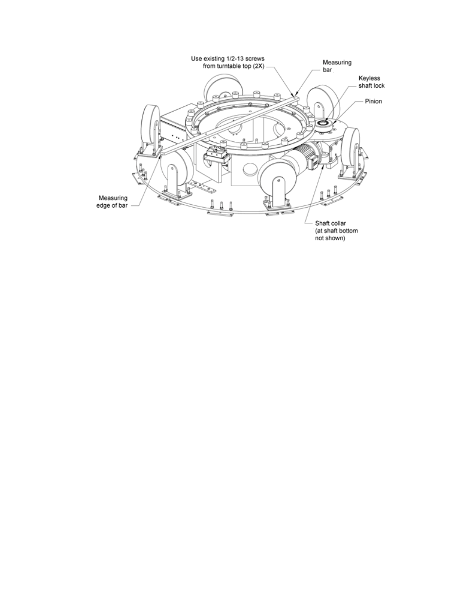
When the turntable is positioned as close as possible to the center, attach the
measuring bar to the brass spacers mounted onto the bearing. Appropriate
hole-mount locations correspond to the size of the turntable. Rotate the bearing
and make sure approximately
7/8-in
to 1-in spacing exists between the edge of
the outer measuring bar and the diameter of hole cut into the pit. Adjust as
required.
The ground ring assembly includes a floor flange with a mounted brush ring that
interfaces with the contact ring mounted beneath the turntable top. The floor
flange provides constant electrical contact with the ground plane.
Mounting methods vary according to user specifications. Clearance holes are
provided at evenly spaced intervals along the outside perimeter of the floor
flange to attach to a customer supplied ground plane. These instructions
describe installation for a paneled floor. For concrete pit mounting instructions
see Floor Flange Installation in Concrete Pit on page 23.
Installing the ground ring assembly requires these tools:
•
1/4-in spacers (3)
• Hand
drill
•
5/32-in drill bit
•
#3 Phillips drive bit
• Small
square
•
#14 x 1 wood/metal screws