Removing the bottom covers and kio3 board – Elecraft KXV3A User Manual
Page 9
9
Hold the KRX3 module by the two brass knurled nuts on the top, and lift it straight up to gain access to the
small TMP coaxial connectors plugged into the module. There are two along the front. There may be one at the
back as well, depending upon the options installed. As you lift the KRX3 module, it will unplug from two small
interface circuit boards. One is at the front and the other is at the rear. These small boards may come out with
the module or they may remain attached to the K3 main RF board.
Unplug the TMP coaxial cables leading to the KRX3 module, then lift the module free and set it aside.
Locate the two small interface circuit boards, remove them and put them in a safe place.
Removing the Bottom Covers and KIO3 Board
If you are replacing a previously-installed KXV3 with the KXV3A, you will not need to remove the
bottom covers and install a new TMP cable or cut jumpers W1 and W2 as described in the following
steps. Simply remove the existing KXV3 board and replace it with the KXV3A using the existing TMP
cable.
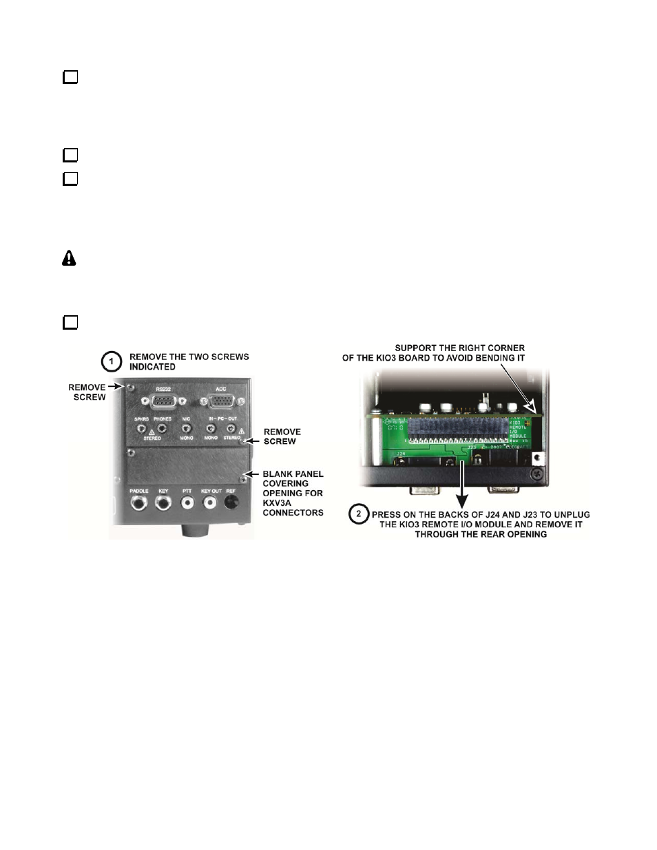
Remove the Digital I/O module from the KIO3 Board at the rear of the K3 as shown in Figure 5.
Figure 5. Removing the Digital I/O Module.