Replacing the top cover – Elecraft KXV3A User Manual
Page 15
15
Replace the screws in the digital I/O daughter board panel as shown in Figure 16.
Figure 16. Mounting the Digital I/O Board and Rear Panel.
If your K3 is equipped with the KRX3 sub receiver, turn to your KRX3 Sub Receiver Installation and
Operation manual, Installing the KRX3 Sub Receiver Module section to replace the KRX3 module. Be
especially careful to do the following as described in that procedure:
Be sure the cover on battery BT1 on the K3 RF board is in place. The cover is essential to avoid
shorting the battery. The outer rim of the battery is the positive terminal, and may come in contact with
the grounded bottom of the KRX3 enclosure if the cover is not in place.
Be sure all the TMP cables are properly connected or your K3 will not operate properly.
Be sure the TMP cable to J85 on the sub receiver module is routed as shown to prevent signal leakage
between the KRX3 and the K3 main receiver.
If your K3 is equipped with the K144XV option and you removed the K144XV module earlier,
replace it and the stiffening bar that runs across the top of the K3 now. Refer to your K144XV manual
for instructions for reconnecting the power and coaxial cables and replacing the module cover. If you
find more cables than shown in the K144XV manual, your unit has the K144 Reference Oscillator Phase
Lock option installed. Refer to that manual to connect the remaining cables.
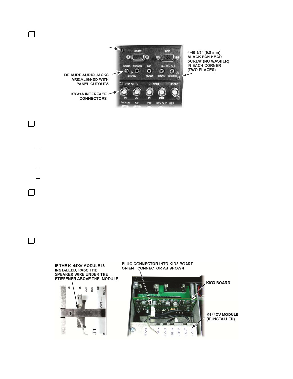
Replacing the Top Cover
Route the speaker wire under the stiffener bar and plug it into the KIO3 board as shown in Figure 17. If
your K3 has the K144XV 2-meter option, route the speaker cable under the stiffener bar at the depression in the
top of the K144XV module as shown in the figure.
Figure 17. Connecting Speaker Cable.