Elecraft KXV3A User Manual
Page 13
13
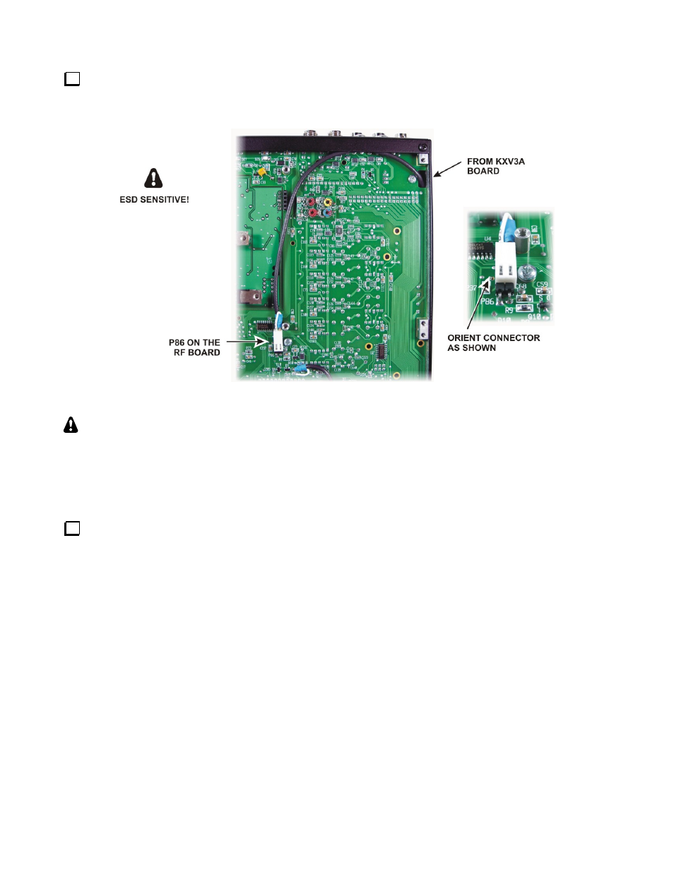
Route the coaxial cable from the KXV3A board to connector P86 on the bottom of the RF board as shown
in Figure 12. Mate the connector to P86 as shown. If the connector does not appear to fit, check to make sure
there are no plastic ridges on the side toward the RF board (see Figure 8).
Figure 12. Routing KXV3A Cable to P86.
SPECIAL NOTE TO KIT BUILDERS:
If you were directed here to install your KXV3A
module as part of the overall kit assembly, installation of the KXV3A module is complete. Return to the
K3 Kit Assembly Manual where you left off.
Reinstalling the KIO3 Board
Replace both bottom covers using the 4-40 black pan head screws you removed earlier. Note that three
locations take the 4-40 1/4” (6.4 mm) black pan head screws with lock washers as shown in Figure 6, while the
remainder are 4-40 3/16” (4.8 mm) screws. Be sure to replace these screws in the correct locations. Make sure
all the screws are secure, but do not over tighten them/
CAUTION!
Failure to replace the three 1/4” (6.4 mm) screws with their lock washers in the
locations shown in
Figure 6
may destroy power transistors in your K3!