Caution – Elecraft KXAT100 Installation Manual User Manual
Page 16
16
CAUTION
When replacing the bottom U-cover in the next step, be sure it is oriented with the lettering
toward the rear panel as shown in Figure 6. Reversing the orientation will cause the
threaded bushings for the handle to strike the circuit boards.
Replace the bottom U-cover so the end with the label nearest the rear panel (the correct orientation is
shown in Figure 6).
Secure the bottom cover with eight screws, four on each side as shown in Figure 6. Do not use lock
washers under these screws.
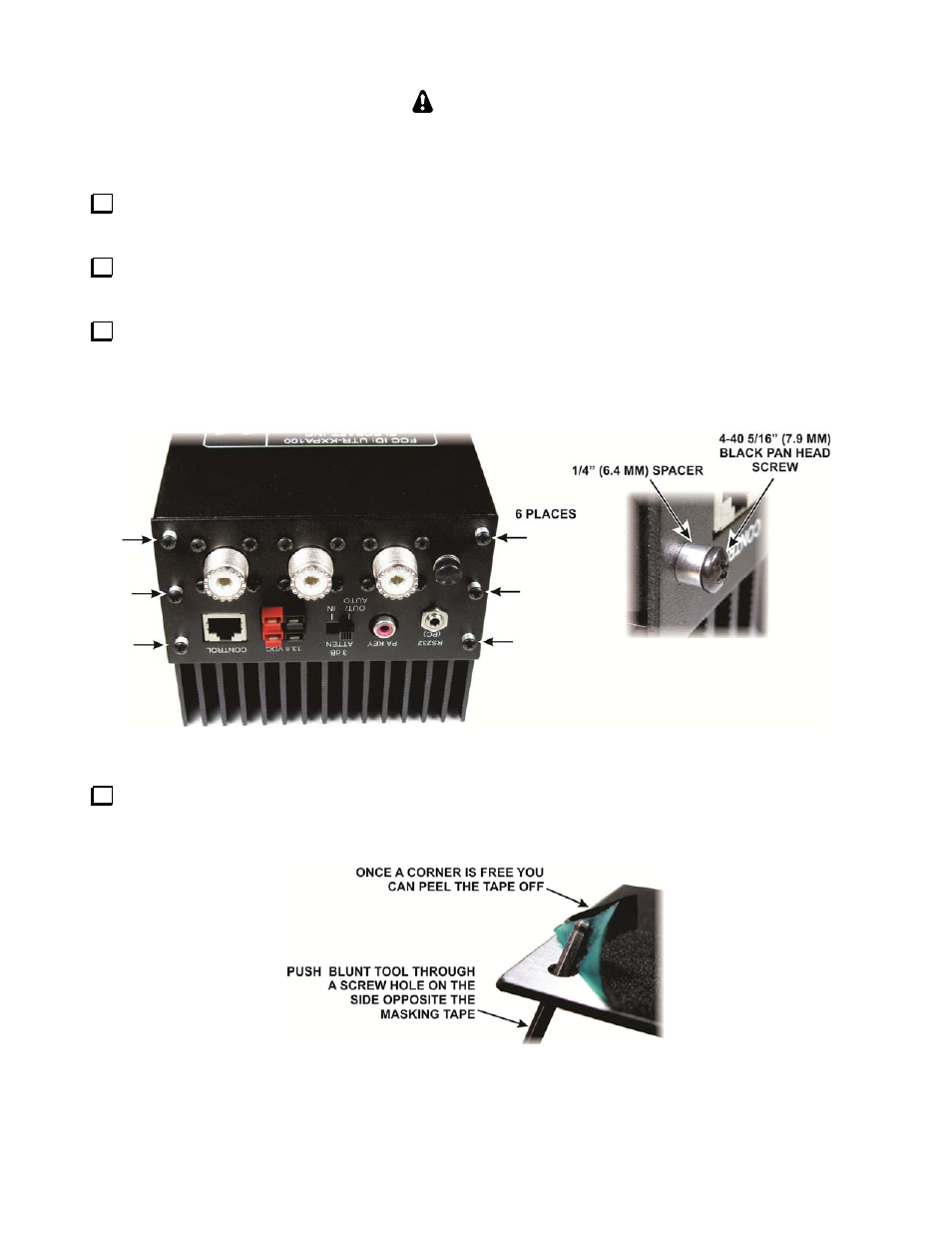
Position the rear panel so the Control, 13.8 VDC, PA Key connectors and the 3 dB ATTEN switch pass
through the openings in the panel as shown in Figure 14. Tuck the cables to the SO-239 connectors in the space
between the circuit board and the cover as needed. Secure the panel with six screws, spacers and lock washers as
shown.
Figure 14. Mounting the Rear Panel.
Unwrap the new front panel. The inside surface should be clean bare metal. It was taped to avoid overspray
during painting. Remove any tape still present. If a large area is taped, you can break it away near one corner
using a blunt tool that fits through a screw hole as shown in Figure 15 and then peel it off of the panel.
Figure 15. Removing Tape from the Front Panel.