Calibration – Elecraft KXFL3 Filter Option User Manual
Page 4
4
Installation Procedure
Disconnect all cables attached to the KX3 and remove the KXPD3 paddles if installed.
Open the KX3 just as you would to install or remove batteries (see Internal Batteries in your
Owner’s Manual for details about how to do this).
Remove the internal batteries (if present).
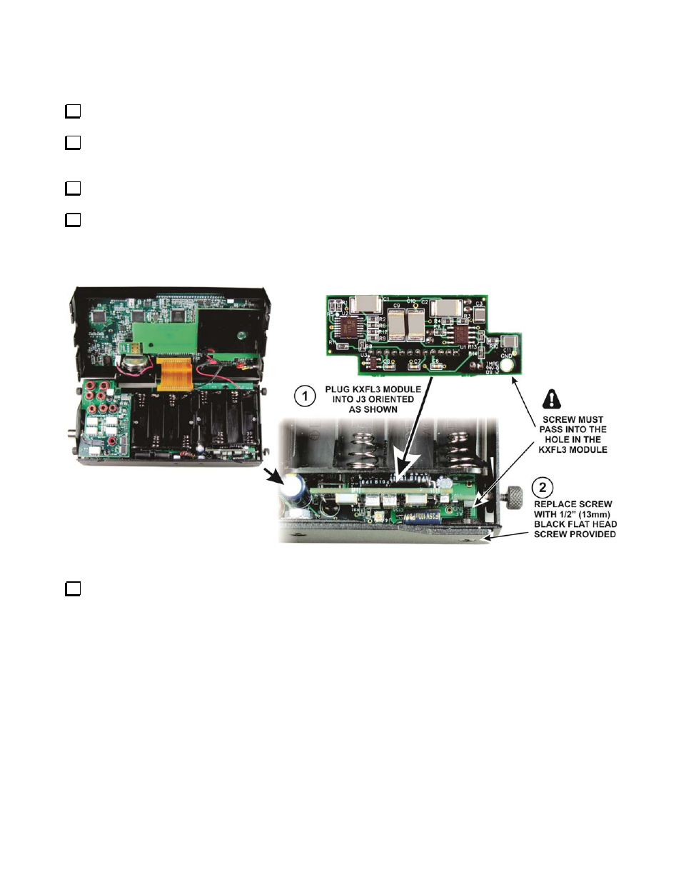
Taking ESD precautions, remove the KXFL3 and plug it into J3 on the KX3 RF board as shown in
Figure 1. The screw is there only to ensure the KXFL3 module cannot be knocked out of its socket by
rough handling of the KX3. It does not provide a ground return or other function.
Figure 1. Installing the KXFL3 Module.
You must run the calibration procedure below for proper filter operation. You can use an external
signal generator to pick up a calibration signal internally. If you do not have an external signal
generator, leave your KX3 open until you have installed the test antenna.
Calibration
Calibration adjusts the gain and phase of each filter to provide optimum rejection of the opposite-sideband
image.
The procedure requires a signal source in the 14-MHz range that can provide a signal level of between
approximately -73 and -33 dBm. This can be provided by an external signal generator such as an Elecraft XG1,
XG2 or XG3. If you do not have a signal generator you can use an internal signal picked up by the antenna
assembly provided with your KXFL3 that will “sniff” adequate signal from a 16 MHz oscillator inside the KX3.