Door frame installation, E) 1/4" & 1/2" glazing adaptors w/ l129 deflector, C) l126 water deflector for 1" glazing – EFCO 960 Series User Manual
Page 41: D) typical detail showing parts relationship, B) glass setting chair assembly, Fig. # 27a, Step 2) step 3) step 1), Fig. # 27
Conc. rod panic
K-153/K-154
& screws
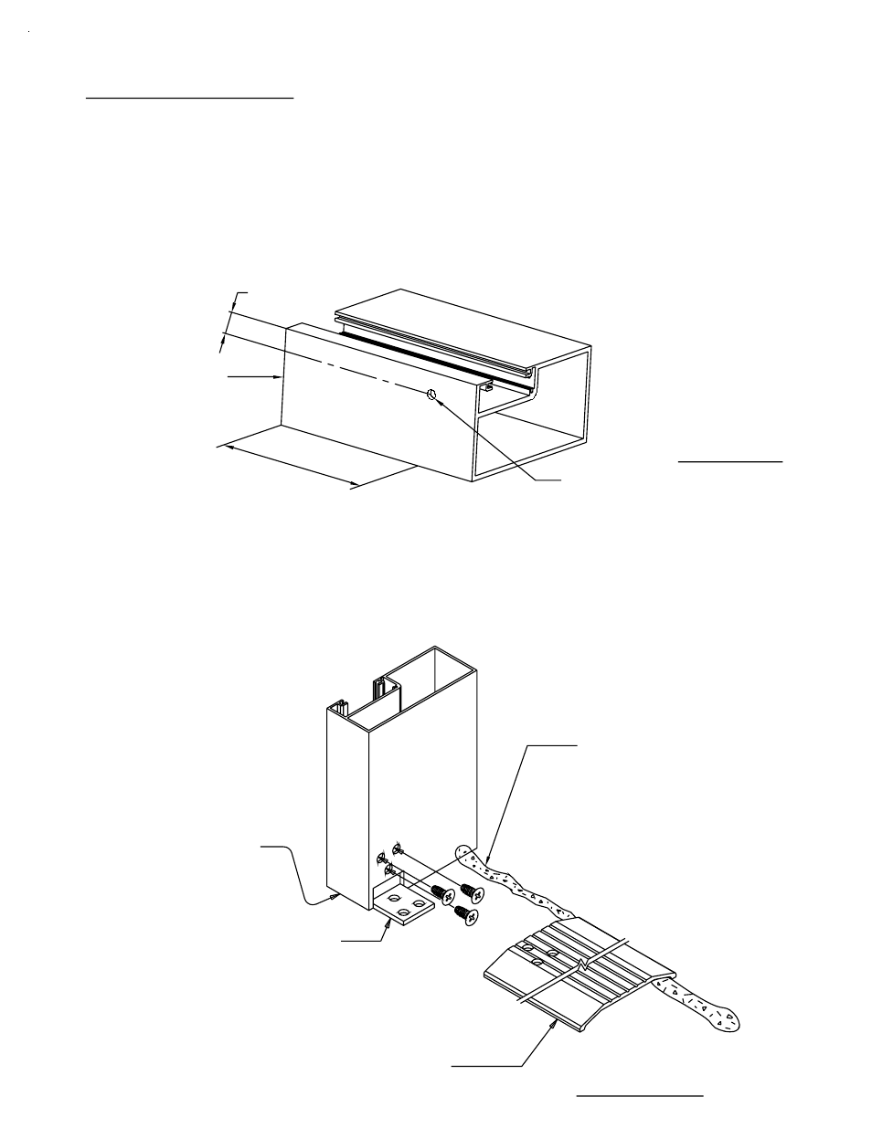
Threshold clip
Threshold clip
& screws
K-124/K-125
NOTE:
FIG. # 27A
(9950 Typ.)
THRESHOLD
Also see Fig. # 28 thru Fig. # 30 on page 40.
NOTE: If NO entrance frame is required, proceed to Section VII.
NOTE: If an entrance frame is required, it must be installed first.
Anchor the door frame as indicated below in Fig. # 27A.
Set the assembled door frame in the opening, plumb and level.
Correctly locate the entrance frame in the opening.
STEP 2)
STEP 3)
STEP 1)
PAGE 39
JDA 3/2002
SECTION VI - DOOR FRAME INSTALLATION
WEEP THE TRANSOM BAR WITH (2) 1/4" DIA. HOLES, 5/8" DOWN
FROM THE TOP AND AT 1/4 POINTS.
#9633 SHOWN,
OTHERS SIMILAR.
JAMB
END
FIG. # 27
960 Wall
1/4" DIA.
.625
1/4 POINT
The door jambs run
to the floor and are
cut longer than other
verticals.
This continuous bead
of sealant runs from
jamb to opposite jamb,
under the threshold and
to the condition or it ties
into the perimeter seal
under the side lite sill
flashing.