Unpacking the linx parts – Dynojet 424 Linx: DWRT Installation Guide User Manual
Page 8
Linx Installation for Model 424 Automotive Dynamometers
4 2 4 L I N X I N S T A L L A T I O N
Unpacking the Linx Parts
4
. . . . . . . . . . . . . . . . . . . . . . . . . . . . . . . . . . .
UNPACKING THE LINX PARTS
Use the following steps to unload your Linx system parts.
1
Using a pry bar, or a large flat screwdriver, and a hammer, carefully remove the
top and sides of the crate. At this point, you will want to inspect the exterior of
the dyno for any indications of damage. Report any damage immediately.
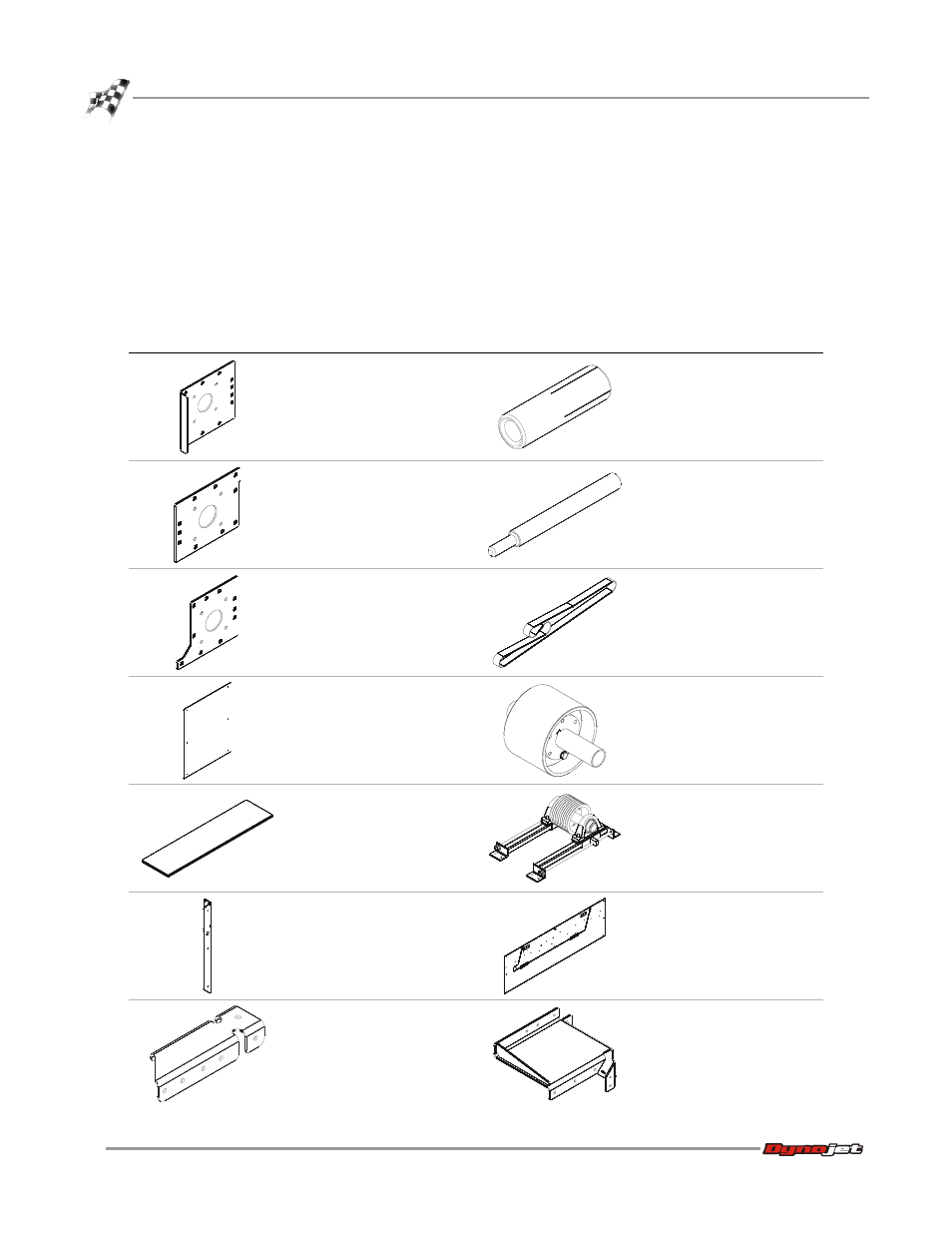
2
Remove the following parts from the crate and set aside.
part
description
part
description
stationary pulley mounting
plate
P/N 21200083
anchor, red head, 3/8" (10
above ground, 6 additional
for in ground, plus 2 extra)
P/N 37513200
moveable pulley mounting
plate
P/N 21200090
installation tool, red head
anchor
P/N 37518200
idler pulley mounting plate
P/N 21200091
v-belt 10/5V3800
P/N 46200007
belt cover, end panel (2)
P/N 21200095
idler pulley assembly
61100007
belt cover, top (2)
P/N 21200097
tensioner assembly
P/N 61100008
belt cover, leg (8)
P/N 21400006
belt cover, front panel
assembly (2)
P/N 61100013
belt cover, center support
P/N 21600026
upper stationary pulley
mount
P/N 61300022