Idler pulley assembly installation – Dynojet 424 Linx: DWRT Installation Guide User Manual
Page 21
4 2 4 L I N X I N S T A L L A T I O N
Idler Pulley Assembly Installation
Version 6
Linx Installation for Model 424 Automotive Dynamometers
17
. . . . . . . . . . . . . . . . . . . . . . . . . . . . . . . . . . .
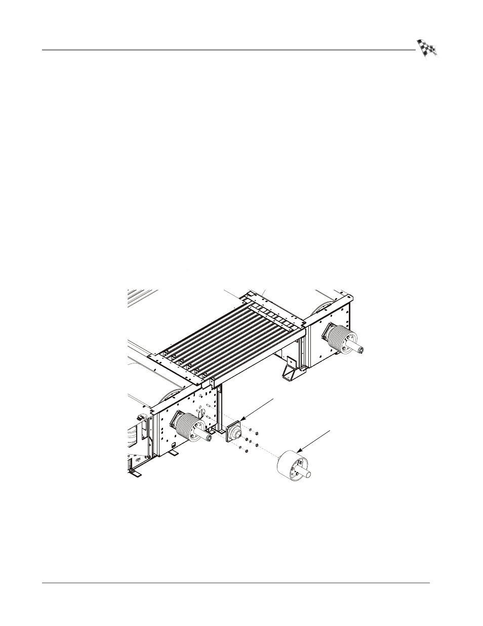
IDLER PULLEY ASSEMBLY INSTALLATION
You will need the following parts:
• 32300001
Flange Bearing with Lock Collar
• 36711100
Nut, 9/16-12, Hex (4)
• 36943101
Washer, 9/16", Flat (4)
• 61100007
Idler Pulley Assembly
1
Place the flange bearing on the threaded studs on the inner plate.
2
Secure the flange bearing to the inner plate using four 9/16-inch flat washers and
four 9/16-inch nuts.
3
Holding the idler assembly horizontal, slide the assembly into the bearing until its
outer edge is approximately 11-1/8-inches from the face of the inner plate.
4
Using the installation instructions included with the bearing, secure the lock
collar.
Note: Refer to the installation instructions included with the bearing.
Carefully allow the idler pulley assembly to hang in the bearing.
Figure 14: Install the Idler Pulley Assembly
XD053
flange bearing
idler pulley assembly
- 150: Kart and ATV Dynamometers (44 pages)
- 150: Dyno Drum Cover for Kart and ATV Dyno Motorcycle Option (3 pages)
- 150: WinPEP 7 (170 pages)
- 168: Eddy Current Brake (27 pages)
- 200: Eddy Current Brake (45 pages)
- 200: Replacing the Starter Ring Gear (7 pages)
- 200: Safety Switch (3 pages)
- 200: DynoWare EX+ Upgrade Installation Guide for Motorcycle Dynos (20 pages)
- 200: Throttle Stop (3 pages)
- 200: Eddy Current Brake Driveline Upgrade (17 pages)
- 200i: High Pressure Blower (20 pages)
- 200: Installation Guide (73 pages)
- 200i: Pit Installation Guide (154 pages)
- 200i: Pre-Installation Guide (52 pages)
- 200i: Installation Guide (184 pages)
- 200i: Air Brake and EEC Kit (40 pages)
- 200i: Dynamometer Wiring Schematic (2 pages)
- 200i: Folding Ramp (15 pages)
- 200i: Control Panel Interface Upgrade (S/N 201xxxx) (31 pages)
- 200i: Control Panel Interface Upgrade (S/N 202xxxx) (29 pages)
- 200i: Motorcycle Exhaust Extraction System Drawings (18 pages)
- 200iP: Pit Installation Guide (148 pages)
- 200iPX: Installation Guide (163 pages)
- 200iPX: Installation Guide (52 pages)
- 200ix: Pit Installation Guide (163 pages)
- 200ix: Extended Carriage and Trike Adapter Assembly (15 pages)
- 200iX: Upgrade Installation Guide (56 pages)
- 200ix: Extended Carriage with Trike Adapter Assembly (13 pages)
- 224: CE Package (17 pages)
- 224: Maintenance Guide (35 pages)
- 224: Installation Guide (78 pages)
- 224/4WD: Installation Guide (77 pages)
- 224: Pit Installation Guide (56 pages)
- 224x: Above Ground Four Post Lift Dimensions (1 page)
- 224x: Pre-Installation Guide (63 pages)
- 224x: 4WD Dyno Air and Wiring Schematic (2 pages)
- 224: Eddy Current Brake (73 pages)
- 224: Pit Eddy Current Brake (69 pages)
- 224xLC2: Quickstart guide for DWRT (2 pages)
- 248: Pit Installation Guide (74 pages)
- 248: Installation Guide (58 pages)
- 248: DynoTRAC User Guide with Variable Brake (14 pages)
- 248: DynoWare EX+ Upgrade (22 pages)
- 248: Optical RPM Sensor (22 pages)
- 248: Proportional Air Brake (21 pages)